Precision Metal Injection Molding Services for Tight-Tolerance Components
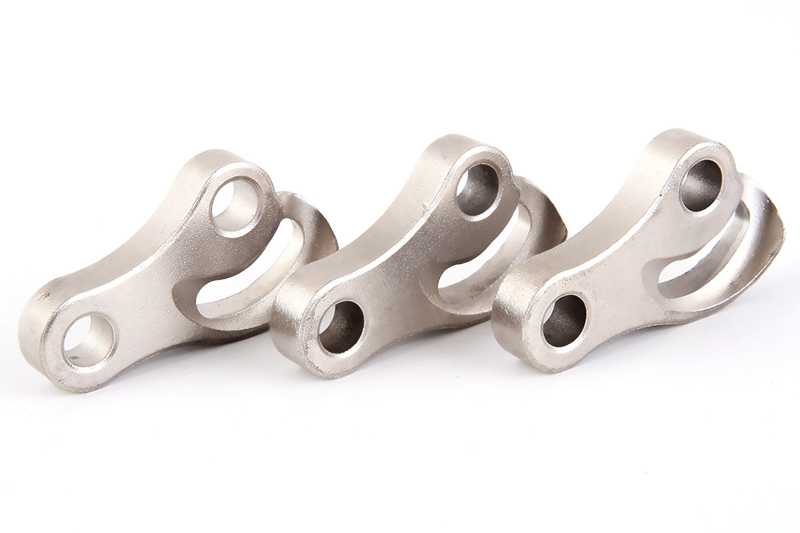
Tight-Tolerance MIM Component RFQ Decision: This article explains how buyers can specify precision metal injection molding for tight-tolerance components that combine small metal geometry with critical datums, holes, contact surfaces, threads, gear features, or assembly interfaces. The part types include miniature gears, lock mechanism parts, medical device features, connector hardware, actuator elements, small stainless steel brackets, and precision sintered components. The practical RFQ problem is deciding which features can remain as-sintered, which features require secondary machining, and which inspection evidence should be quoted before the buyer validates fit, movement, wear, corrosion exposure, and production consistency.
Tight-tolerance MIM performance depends on the full process route. Feedstock quality, mold filling, debinding, sintering shrinkage, fixture support, material grade, and post-processing can all affect final dimensions. Buyers should mark critical-to-function features on the drawing instead of applying tight tolerances to every surface, because over-controlling non-functional features can obscure the real manufacturing risk.
Which MIM Features Actually Need Tight Tolerances?
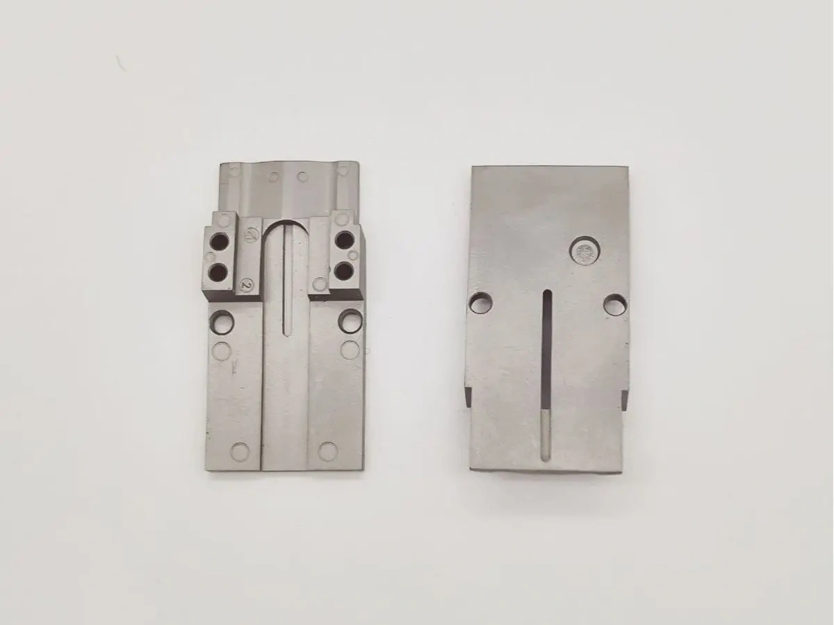
The RFQ should identify the features that control function. A gear bore, pivot hole, sliding face, thread, sealing surface, datum plane, and mating boss may need tighter control than an exterior non-contact wall. Buyers should define whether the feature controls assembly, rotation, backlash, sealing, electrical contact, or wear behavior.
This distinction helps the supplier decide whether MIM alone is suitable or whether machining, reaming, tapping, grinding, calibration, or polishing should be included after sintering. Tight tolerance should be a functional requirement tied to a part feature, not a blanket instruction across the full drawing.
Tight-Tolerance Feature | Manufacturing Concern | Likely Control Method | Inspection Evidence |
|---|---|---|---|
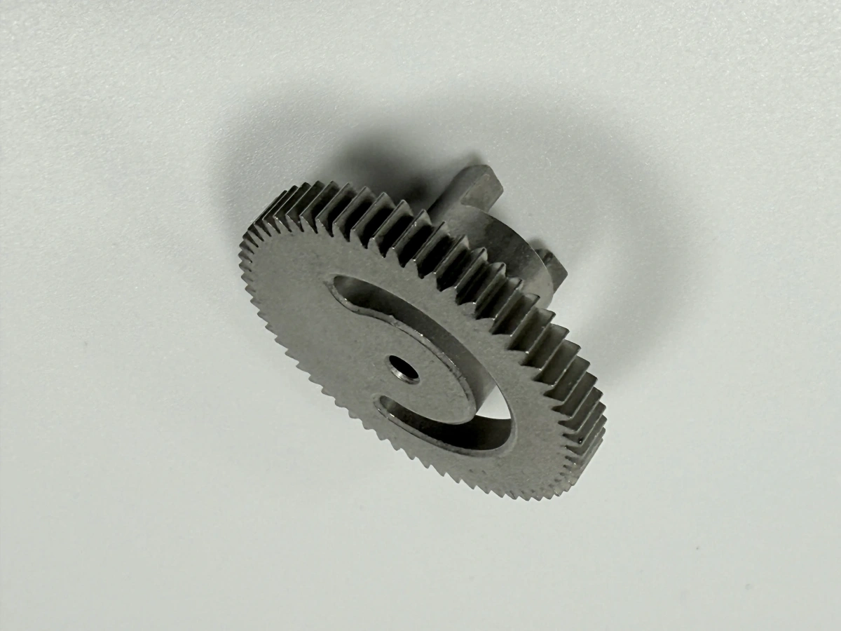
Gear bore or pivot hole | Shrinkage, roundness, location, fit with shaft | As-sintered review plus possible reaming or machining | CMM or bore inspection report |
Datum face or mounting surface | Flatness, parallelism, assembly stack-up | Fixture planning or post-sintering machining | CMM report and surface finish inspection |
Threaded feature | Thread form, pull-out behavior, burr control | Tapping or thread-forming after sintering | Thread gauge and dimensional inspection |
Sliding or sealing contact | Surface finish, wear, edge condition | Polishing, grinding, machining, or surface treatment | Surface finish and functional fit review |
How Does MIM Shrinkage Affect Dimensional Control?
MIM shrinkage is expected during sintering, so dimensional control begins before production tooling is released. Tooling, feedstock, molded green-part stability, debinding, sintering support, and material behavior all influence final size. Buyers should state which dimensions are critical after sintering and which surfaces can accept normal process variation.
The RFQ should include drawings that identify datum schemes and critical dimensions. It should also state whether the part will be inspected as a prototype sample, first article, pilot lot, or recurring production part. Relevant process background includes metal sintering in MIM production, pressureless sintering in MIM, and MIM mold design considerations.
Which Materials Are Suitable For Precision MIM Components?
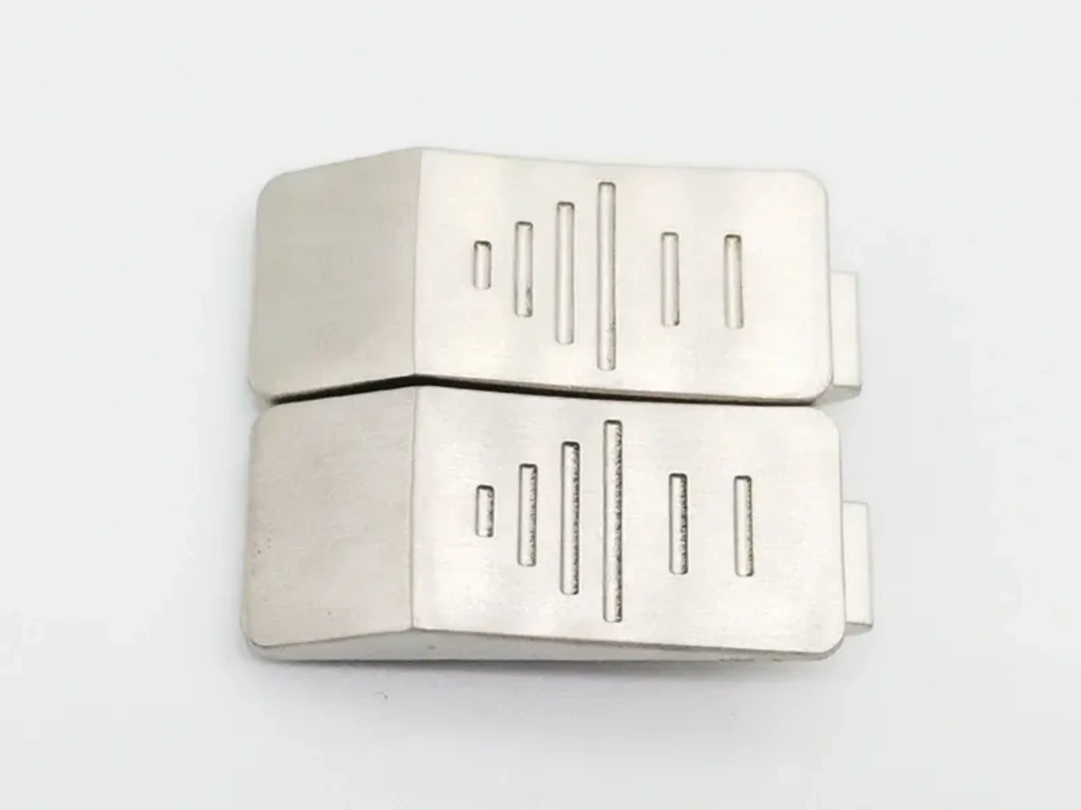
Material selection should be connected to the part function. Stainless steels may be reviewed for corrosion-resistant precision parts. Low alloy steels may be reviewed for strength and heat treatment response. Tool steels may be reviewed for wear-loaded mechanisms. Magnetic alloys may be reviewed for electromagnetic features. The material must be selected before final tolerance planning because sintering behavior, hardness, finishing, and secondary machining can vary by grade.
Buyers can compare MIM 17-4 PH stainless steel, MIM 316L stainless steel, MIM 420 stainless steel, MIM 440C stainless steel, MIM 4140 alloy steel, and MIM materials and properties when defining precision component requirements.
When Should Secondary Machining Be Included?
Secondary machining should be included when a feature controls fit, motion, sealing, bearing contact, or thread engagement beyond what the as-sintered MIM route can reasonably support. Post-sintering machining may include drilling, reaming, tapping, milling, turning, grinding, polishing, or calibration. The buyer should identify which features require machining and which features can remain as-sintered.
This decision affects cost and inspection. A MIM part with one machined datum may be a good production route, while a part requiring heavy machining on most features may need process comparison with CNC machining or casting. Buyers can use precision MIM services for tight-tolerance components and MIM versus CNC machining and casting to frame route decisions.
How Should Tooling And Design Rules Be Reviewed?
Tooling and design rules should be reviewed around critical features. Wall thickness, ribs, bosses, hole locations, undercuts, sharp corners, gate location, parting line, and ejector marks can affect dimensional control. Small MIM parts can be especially sensitive to uneven sections because shrinkage and distortion may concentrate around transitions.
The RFQ should include a DFM request for critical dimensions. Buyers should identify any features that cannot be moved for mold parting or sintering support. Complex MIM geometry guidance and MIM design, tolerances, and cost factors can support the design review.
RFQ Control Area | Entity To Specify | Buyer Decision Supported |
|---|---|---|
Critical dimension | Datum, hole, slot, bore, thread, gear feature | As-sintered tolerance versus secondary machining |
Shrinkage-sensitive geometry | Wall transition, rib, boss, thin feature, asymmetric section | Tooling review and sintering support planning |
Material behavior | 17-4 PH, 316L, 420, 440C, 4140, heat treatment | Dimensional stability and finishing route |
Inspection evidence | CMM, gauge, surface finish, hardness, material record | First article and production release |
What Inspection Evidence Should Support Tight-Tolerance MIM?
Inspection evidence should match the tolerance risk. CMM inspection can support datums, hole locations, gear features, slots, and mounting surfaces. Gauge inspection can support threads, bores, and fit features. Surface finish inspection can support sliding or sealing surfaces. Hardness and material records can support heat-treated or wear-loaded MIM parts.
The RFQ should state the inspection stage and sample expectation. Prototype inspection, first article inspection, pilot lot inspection, and recurring production sampling have different purposes. Buyers should also state which final tests remain under buyer validation, such as fit, torque, wear, corrosion, or functional cycle testing. References such as CMM dimensional inspection and industrial CT defect inspection can support inspection planning.
What Should Buyers Include In A Tight-Tolerance MIM RFQ?
A complete RFQ should include CAD files, 2D drawings, part function, target material, critical dimensions, datum scheme, shrinkage-sensitive features, secondary machining requirements, heat treatment, surface treatment, inspection reports, production stage, and buyer validation requirements. Buyers should mark functional features and separate them from cosmetic or non-contact surfaces.
Important decisions should be stated directly. If a bore must be machined, mark the bore as machined after sintering. If a surface can remain as-sintered, state that requirement clearly. If the buyer needs proof of production consistency, define the sampling and inspection records. If the buyer is comparing MIM with CNC machining, state the part volume stage and which features make MIM attractive.
Related FAQs
What tolerances can precision metal injection molding services typically achieve?
How are tight-tolerance components controlled during the MIM shrinkage process?
Which design factors affect dimensional accuracy in precision MIM parts?
Can secondary machining improve tolerances for metal injection molded components?
What quality inspection methods are used for tight-tolerance MIM components?
How is dimensional consistency controlled in mass production?