What is Pressureless Sintering in Metal Injection Molding (MIM)?
This article explains pressureless sintering in metal injection molding (MIM), the furnace stage that converts debound brown parts into sintered metal components without external pressing pressure. For RFQs on small stainless steel, low alloy steel, tungsten alloy, titanium alloy, or magnetic alloy MIM parts, the practical problem is deciding whether as-sintered dimensions, shrinkage, density, surface condition, secondary machining, and inspection evidence can meet the drawing requirement.
Pressureless Sintering in the MIM Process Route
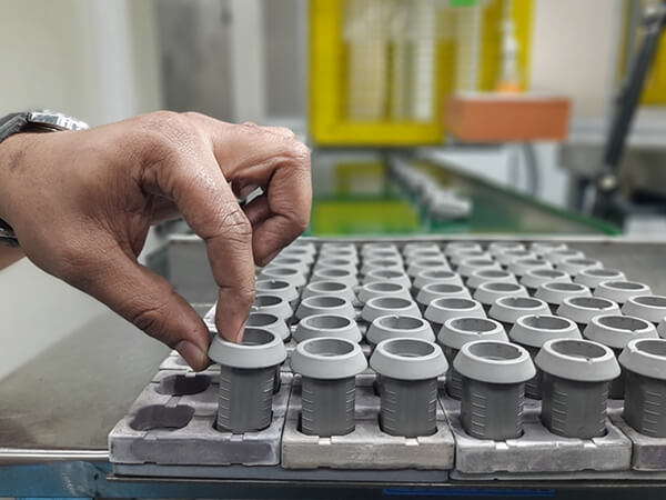
Pressureless sintering is the high-temperature densification stage used after molding and debinding in metal injection molding. The molded green part contains metal powder and binder. Debinding removes most of the binder and leaves a fragile brown part. Pressureless sintering then bonds the metal particles in a controlled furnace atmosphere.
The word pressureless matters because the furnace stage does not use a die to press the part into final shape. The part must be supported, heated, held, cooled, and inspected in a way that controls shrinkage and distortion. The sintered shape depends on powder, binder removal, furnace profile, material grade, part geometry, and fixture support.
How Debinding, Brown Parts, and Sintering Shrinkage Work Together
MIM sintering cannot be separated from debinding. If binder removal leaves residue, cracks, blisters, or weak areas, pressureless sintering may amplify those defects. If debinding is stable, sintering can densify the part more predictably and reduce the risk of internal voids, uneven shrinkage, or surface contamination.
Shrinkage is expected in MIM because the binder volume is removed and metal particles move closer together during sintering. Buyers should not treat the molded dimension as the final dimension. Tooling compensation, material feedstock behavior, furnace cycle, and inspection feedback all help control the final sintered size.
MIM Production Stage | What Happens | Manufacturing Risk | Buyer Confirmation Needed |
|---|---|---|---|
Feedstock preparation | Metal powder is mixed with binder into moldable feedstock | Powder size, binder content, and lot consistency affect flow and shrinkage | Material grade, critical features, and expected production quantity |
Injection molding | Feedstock fills the mold cavity and forms a green part | Gate location, weld lines, sink risk, and thin features can affect shape | 3D model, drawing, datum scheme, and cosmetic surface notes |
Debinding | Binder is removed before high-temperature sintering | Cracks, residue, and weak brown parts can lead to sintering defects | Part thickness, internal features, and acceptance criteria |
Pressureless sintering | Metal particles bond and the part densifies in a furnace | Shrinkage, warpage, porosity, and surface condition must be controlled | Critical dimensions, inspection method, and secondary operation needs |
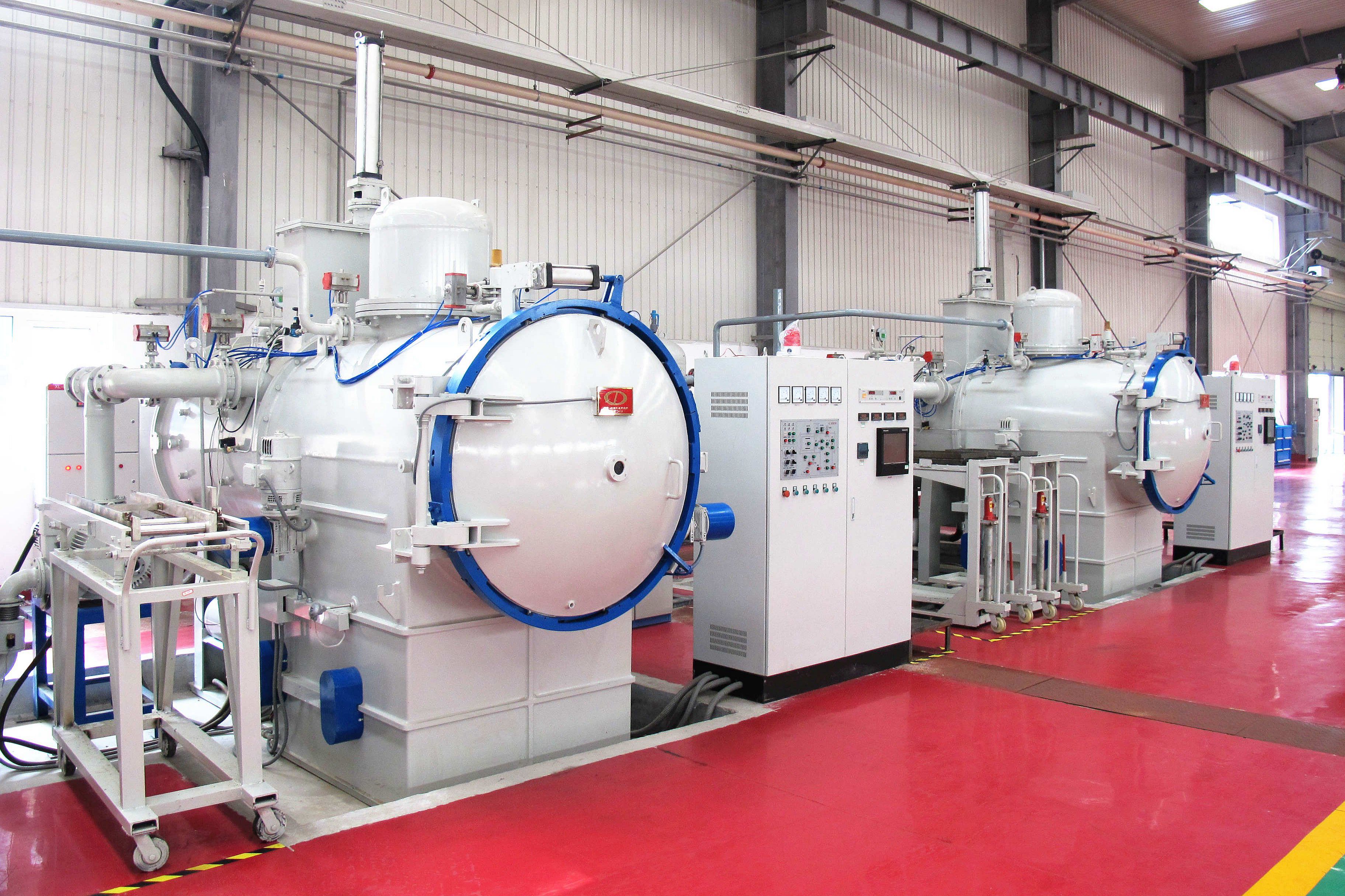
Furnace Atmosphere, Temperature Profile, and Support Fixtures
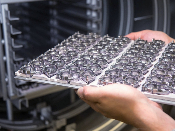
Pressureless sintering depends on furnace atmosphere, temperature ramp, hold time, cooling rate, and part support. These settings are selected according to the material family and feedstock. Stainless steel, low alloy steel, tungsten alloy, magnetic alloy, and titanium alloy MIM parts can require different atmosphere and contamination controls.
Support fixtures also matter. A thin wall, long arm, cantilevered tab, or asymmetric mass can sag or distort during sintering. Ceramic setters, trays, spacing, part orientation, and furnace loading pattern should be reviewed when the drawing includes flatness, perpendicularity, concentricity, sealing faces, or cosmetic surfaces.
Shrinkage, Distortion, Porosity, and Density Risks in Sintered MIM Parts
The main pressureless sintering risks are dimensional shrinkage, nonuniform distortion, residual porosity, surface contamination, and material property variation. These risks are not only furnace issues. They can begin with powder manufacturing, feedstock mixing, mold filling, debinding, support design, or part geometry.
For tight MIM features, buyers should identify which dimensions are functional and which surfaces are reference datums. A part may be acceptable as-sintered for many features but still need CNC machining, grinding, sizing, reaming, tapping, heat treatment, or surface finishing for datum faces, holes, sealing features, threads, or wear surfaces.
Pressureless Sintering Compared With Hot Pressing, Powder Pressing, CNC, and Metal 3D Printing
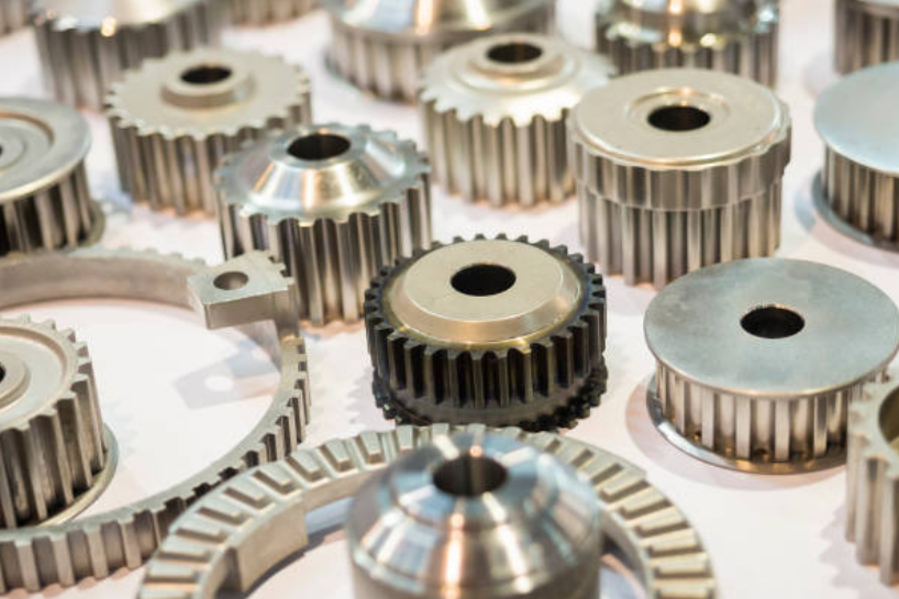
Pressureless sintering in MIM is suitable when small complex metal parts can justify mold tooling and shrinkage control. Hot pressing sintering uses pressure during densification and may fit some ceramics or powder materials, but it does not replace MIM for every small molded metal geometry. Powder pressing molding can be suitable for more press-friendly shapes but is limited by compaction direction and feature complexity.
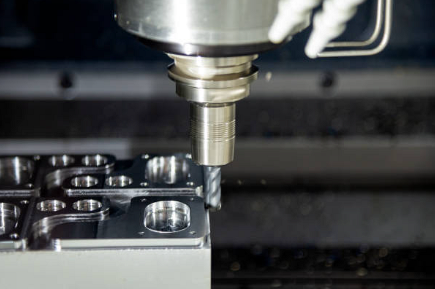
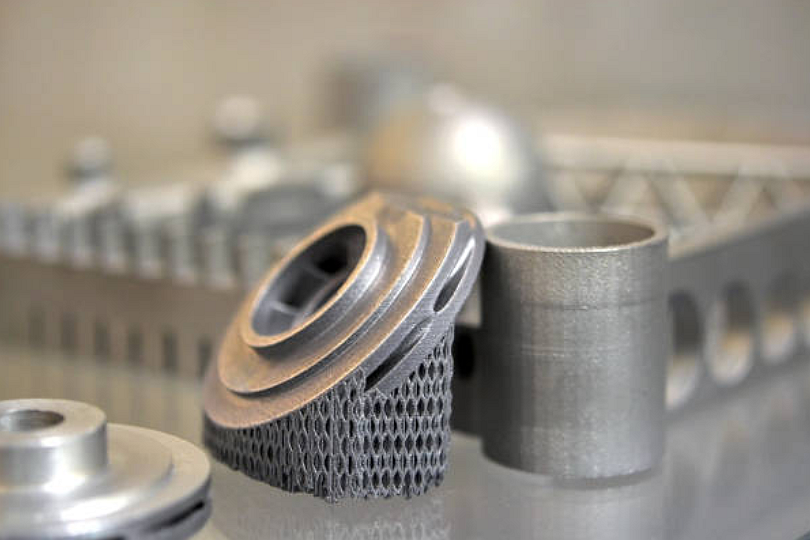
CNC machining may be better for prototypes, low quantities, tight machined datums, and parts where tooling is not justified. Metal 3D printing may be better for very complex internal channels or early design iteration. MIM can be better when small complex metal parts need repeatable production after tooling, feedstock, and sintering behavior are validated.
Manufacturing Route | Best Fit | Key Limitation | RFQ Review Point |
|---|---|---|---|
MIM pressureless sintering | Small complex metal parts made from molded feedstock | Shrinkage, tooling, debinding, and sintering validation are required | Confirm material grade, annual quantity, critical dimensions, and inspection plan |
Hot pressing sintering | Selected powder or ceramic parts needing pressure-assisted densification | Shape freedom and tooling approach differ from MIM | Confirm whether pressure-assisted tooling suits the geometry |
CNC machining | Prototype parts, machined datums, threads, and low-volume precision parts | Complex small internal features can increase machining time | Confirm datum surfaces, tool access, material, and surface finish |
Metal 3D printing | Complex prototypes, internal channels, and design iteration | Surface, density, support removal, and post-machining may be needed | Confirm functional surfaces, post-processing, and inspection criteria |
Secondary CNC Machining and Metal 3D Printing in Route Selection
Secondary CNC machining is often reviewed after pressureless sintering when a MIM part has threaded holes, bearing surfaces, sealing faces, precision datums, or assembly interfaces. These features may be molded near-net shape and then machined after sintering to reduce functional risk.
Metal 3D printing is not a direct substitute for pressureless sintering in every RFQ. It can support prototype learning, internal channels, or geometry checks, while MIM may be more suitable after the design is stable and production quantity can support tooling. The route decision should compare material, surface condition, dimensional evidence, quantity, and post-processing rather than only the visible part shape.
Materials, Secondary Operations, and Inspection After MIM Sintering
Material selection should be reviewed before tooling because powder, binder, debinding, and sintering conditions change by grade. Common MIM materials include stainless steels, low alloy steels, tool steels, magnetic alloys, tungsten alloys, titanium alloys, and cobalt alloys. Each material family can have different shrinkage behavior, furnace control needs, and secondary operation requirements.
Inspection after pressureless sintering may include dimensional reports, CMM inspection, density checks, hardness testing, visual inspection, thread gauges, surface roughness checks, and buyer-defined functional tests. If a MIM part needs heat treatment, passivation, plating, coating, polishing, or assembly, those operations should be included in the RFQ rather than discovered after sampling.
Related FAQs
10 Reasons Why MIM Metal Powders Are More Expensive Than Common Bulk Metal Materials?
Which materials are suitable for metal injection molding (MIM)?
What tolerances can precision metal injection molding services typically achieve?
How are tight-tolerance components controlled during the MIM shrinkage process?
Can secondary machining improve tolerances for metal injection molded components?
What quality inspection methods are used for tight-tolerance MIM components?
What cost advantages does the MIM process offer compared with CNC machining?