What Is The Shrinkage of Metal Injection Molding?
Metal Injection Molding shrinkage is the controlled dimensional reduction that occurs as a molded green part becomes a dense sintered metal part through debinding and sintering. The practical RFQ problem is deciding how the MIM material, feedstock, part geometry, tool compensation, sintering process, and inspection plan will control critical dimensions on small complex metal parts.
What does shrinkage mean in Metal Injection Molding?
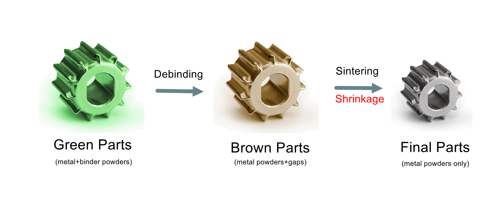
In Metal Injection Molding, shrinkage means that the injected feedstock shape becomes smaller as binder is removed and metal powder particles densify during sintering. The molded green part is intentionally made larger than the final metal part because the mold and process plan must compensate for this expected dimensional change.
Shrinkage is not a random defect when the MIM process is controlled. Shrinkage is a normal part of the MIM route. The risk for buyers is uneven shrinkage, unpredictable distortion, or uncontrolled dimensional change on features such as holes, slots, thin walls, threads, bosses, datum faces, and mating surfaces.
MIM shrinkage factor | Manufacturing stage affected | Dimensional risk | RFQ information buyers should provide |
|---|---|---|---|
Metal powder type | Feedstock preparation and sintering | Different alloys and powder characteristics can shrink differently | Target alloy grade and any approved substitute material |
Binder system | Injection molding and debinding | Binder removal can affect shape stability before sintering | Functional surfaces and fragile features |
Powder loading | Feedstock consistency | Variation can affect final density and dimensional trend | Critical dimensions and inspection priority |
Part wall thickness | Debinding, heating, and sintering | Thick and thin sections may shrink or distort differently | Wall thickness, ribs, bosses, and section changes |
Feature geometry | Tooling, debinding, and sintering support | Small holes, long slots, thin posts, and deep features can move or close | Functional holes, slots, threads, and assembly interfaces |
Sintering support | Sintering furnace loading | Unsupported features may sag, warp, or distort | Flatness, straightness, and datum requirements |
Tool compensation | Mold design | Wrong compensation can cause systematic oversize or undersize parts | 2D drawing, tolerance scheme, and final inspection dimensions |
Secondary machining | Post-sintering finishing | Critical features may still need machining after shrinkage | Machined datum surfaces, threads, bores, or sealing faces |
When does shrinkage occur during the MIM process?
MIM shrinkage mainly becomes visible during sintering, after the molded green part has passed through debinding. The green part contains metal powder and binder. Debinding removes the binder system, leaving a fragile brown part that must retain enough shape for sintering.
During sintering, metal powder particles bond together and densify. This densification reduces the part's overall dimensions and creates the final metal structure. The shrinkage direction and consistency depend on powder, binder, part geometry, support, furnace conditions, and process control.
The buyer should understand that the mold cavity is not the same size as the final part. The MIM supplier designs the mold with shrinkage compensation so the sintered part can reach the target dimensions after the expected reduction.
How do material, feedstock, and part geometry affect MIM shrinkage?
Material and feedstock affect shrinkage because each MIM alloy and powder system has its own sintering behavior. Stainless steel, low-alloy steel, tool steel, magnetic alloys, and other MIM materials may require different processing assumptions. The exact shrinkage factor should be confirmed by the supplier for the selected material and feedstock system.
Part geometry also affects shrinkage. A uniform wall section is usually easier to control than a part with abrupt section changes, isolated thick bosses, thin cantilevers, long slots, blind holes, or very small features. Uneven mass distribution can increase distortion risk during debinding and sintering.
Buyers should identify functional dimensions early. A cosmetic outside profile may tolerate more variation than a bearing bore, snap feature, threaded hole, sealing surface, gear tooth, or mating datum. That distinction helps the supplier plan tooling, sintering support, inspection, and possible secondary machining.
How does shrinkage affect MIM dimensions and tolerances?
Shrinkage affects both overall part size and local feature accuracy. Even when global shrinkage is predicted, individual features can be influenced by gate location, wall thickness, debinding path, sintering support, furnace loading, and part orientation.
For MIM RFQs, buyers should avoid assigning tight tolerance to every feature by default. Tight tolerance should be reserved for functional dimensions such as mating surfaces, holes, bores, thread locations, sealing areas, alignment features, and datum surfaces. Nonfunctional dimensions can often use broader tolerance expectations.
If a dimension is too critical for as-sintered MIM control, secondary machining, coining, sizing, grinding, or another finishing operation may be needed. The drawing should make those critical features clear so the quote includes the correct process route.
How do tooling and process control compensate for MIM shrinkage?
MIM tooling compensates for shrinkage by scaling the mold cavity and adjusting feature design according to the selected feedstock and sintering process. This compensation is based on process experience, material data, mold flow behavior, and dimensional feedback from sampling.
Process control supports this compensation. Feedstock consistency, injection molding conditions, debinding cycle, sintering temperature profile, furnace atmosphere, part support, and inspection feedback all affect dimensional consistency. A stable process helps the supplier keep shrinkage behavior predictable from sampling to production.
Inspection closes the loop. First article inspection, CMM measurement, gauge checks, visual inspection, density review, and functional testing can identify whether shrinkage compensation is correct or whether tooling, process, or secondary operations need adjustment.
What should buyers provide when MIM shrinkage is a quotation concern?
A useful MIM RFQ should include the 3D CAD model, 2D drawing, target alloy, expected quantity, part function, critical dimensions, tolerance notes, surface finish requirements, heat treatment or secondary operation needs, inspection requirements, and any assembly interfaces that cannot be changed.
Buyers should also mark dimensions that are critical after sintering. If holes will be drilled after sintering, if threads will be machined, if a datum will be ground, or if a surface will be polished, those operations should be stated before quotation.
The practical answer is that MIM shrinkage is expected and manageable when material selection, tool compensation, debinding, sintering, inspection, and secondary operations are planned together. The exact shrinkage value should be treated as project-specific rather than copied from a general rule.
Related FAQs