What is Metal Injection Molding? How does It work?
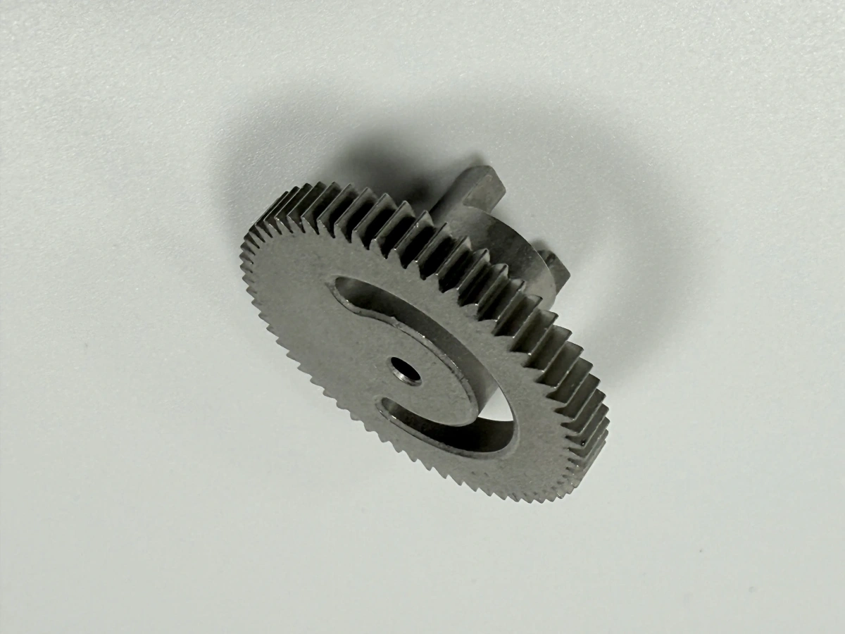
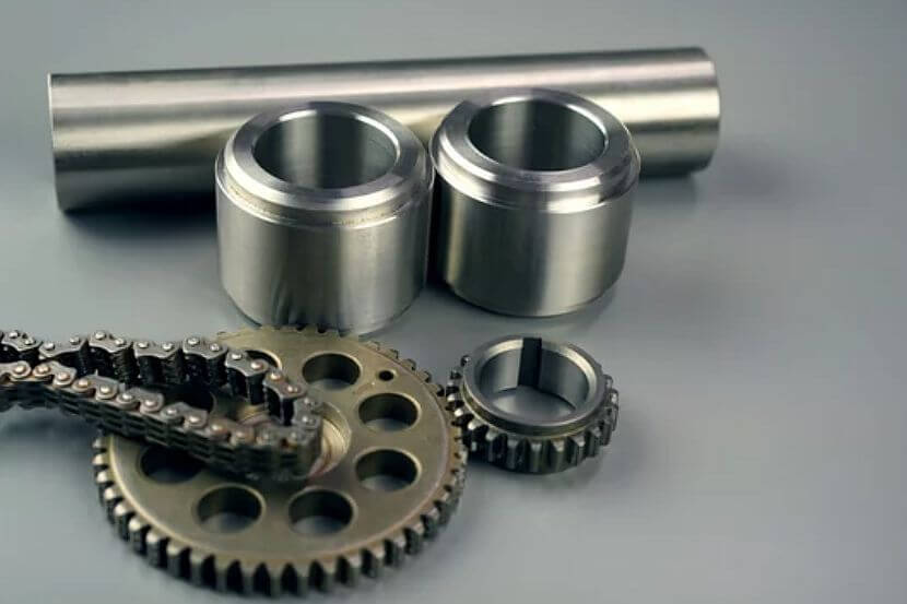
Metal injection molding (MIM) is a powder metallurgy and injection molding manufacturing process for small, complex metal parts such as gears, hinges, lock components, medical instrument components, electronic hardware, and automotive mechanisms. This article explains how MIM converts metal powder feedstock into sintered metal parts and helps buyers decide whether MIM, CNC machining, investment casting, die casting, or stamping is the better manufacturing route. The practical RFQ problem is that a MIM quotation depends on material grade, annual volume, shrinkage control, critical dimensions, secondary operations, and inspection criteria, not only on the visible part shape.
Short answer: MIM is usually most useful when a metal part is too complex or too costly for repeated CNC machining, but the part is small enough and the production quantity is high enough to justify tooling and sintering process control. Buyers should define the drawing, 3D model, material grade, datum surfaces, thread or bore requirements, surface finish, heat treatment, and inspection evidence before a MIM tooling review.
Process Stage | What Happens | Risk to Control | Buyer Confirmation Needed |
|---|---|---|---|
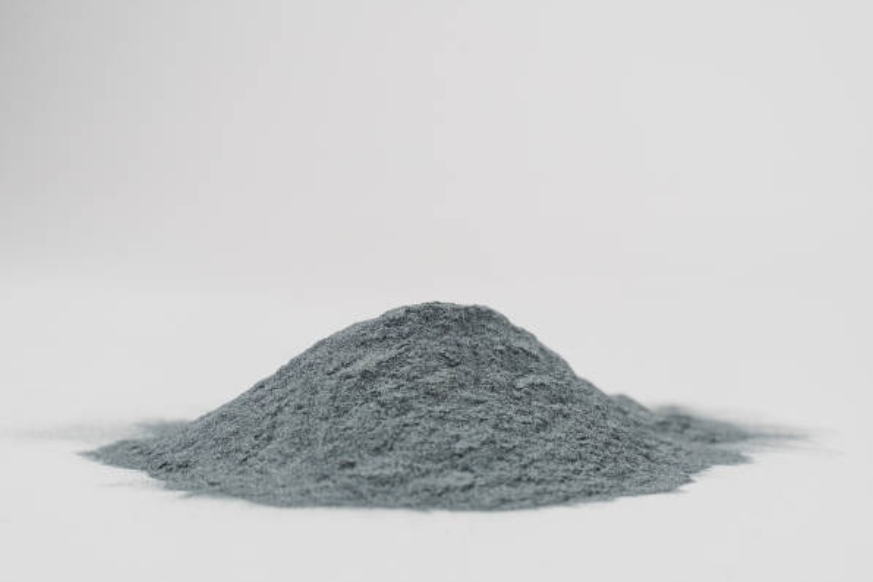
Metal powder selection | Fine powder is selected for the required alloy family, such as 316L stainless steel, 17-4 PH stainless steel, MIM-420 stainless steel, Ti-6Al-4V, tungsten alloy, or cobalt alloy. | Powder chemistry, particle size, contamination, and material availability affect sintering behavior and final properties. | Material grade, applicable standard, corrosion or hardness requirement, and documentation requirement. |
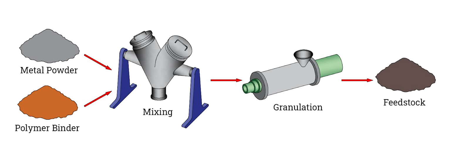
Feedstock compounding | Metal powder is mixed with polymer binder so the feedstock can flow into an injection mold cavity. | Binder ratio and powder loading influence mold filling, debinding stability, shrinkage, and density. | Part size, wall thickness range, cosmetic surfaces, gate location sensitivity, and expected production quantity. |
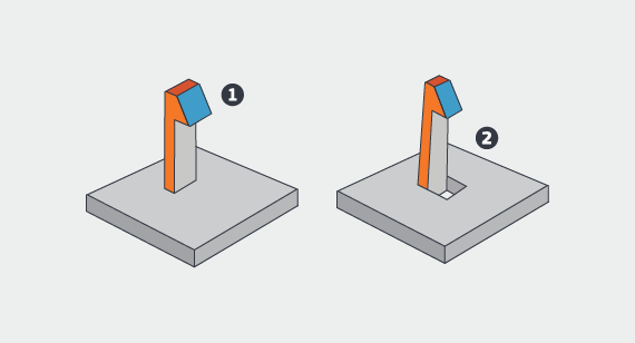
Injection molding | The feedstock is molded into a green part with the near-net geometry of the final component. | Thin sections, undercuts, sharp corners, long flow paths, and uneven wall sections can create molding risk. | Critical surfaces, molded threads, holes, gear teeth, undercuts, and features that cannot change after design review. |
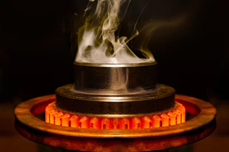
Debinding and sintering | Binder is removed, then the brown part is sintered so metal particles bond into a dense metal component. | Sintering shrinkage, distortion, density variation, and support method can affect dimensional control. | Critical tolerance zones, datum strategy, inspection method, and any surfaces that may need machining allowance. |
Secondary operations and inspection | Heat treatment, CNC machining, polishing, passivation, coating, plating, or assembly may be added after sintering. | Post-processing can change hardness, surface roughness, coating thickness, fit, appearance, and acceptance risk. | FAI, CMM report, material certificate, hardness test, surface roughness report, coating thickness report, or visual standard. |
What Is Metal Injection Molding for Small Complex Metal Parts?
Metal injection molding is a near-net-shape process for producing small metal components with complex geometry. The process combines principles from powder metallurgy and plastic injection molding: metal powder provides the final alloy, and binder temporarily gives the powder mixture enough flow to fill a mold.
MIM fits parts that need internal features, thin sections, small holes, splines, gear teeth, undercuts, or repeated production after tooling approval. Typical MIM part families include lock hardware, electronic connectors, watch and hinge components, small medical instrument components, automotive mechanisms, and industrial wear parts. For regulated or performance-critical applications, buyer specifications, qualification requirements, and acceptance criteria should be defined before production approval; final validation remains the buyer's responsibility.
How Metal Injection Molding Converts Feedstock Into Sintered Metal Parts
The MIM process changes metal powder feedstock into a finished metal part through powder preparation, feedstock compounding, injection molding, debinding, sintering, and secondary operations. Each stage affects shrinkage, density, surface condition, and dimensional inspection.
MIM Metal Powder Preparation
Metal powder selection controls the starting material for the process. The powder must match the alloy family and the performance target of the final component. Stainless steel grades such as 316L, 17-4 PH, and MIM-420 are common MIM choices, while alloys such as Ti-6Al-4V, MP35N, tungsten alloy, and cobalt alloy require more specific review of powder availability and processing behavior.
Feedstock Compounding and Mold Filling
After powder preparation, metal powder is mixed with binder to create MIM feedstock. The feedstock must flow into the mold cavity while maintaining enough powder loading for sintering. This is why part geometry, gate location, wall thickness balance, and molded feature design are reviewed before tooling.
Debinding and Sintering Shrinkage
Debinding removes binder from the molded green part and leaves a brown part that can be sintered. During pressureless sintering or another approved sintering route, metal particles bond together and the part shrinks. The tooling design must compensate for expected MIM shrinkage, but critical dimensions still need drawing-based tolerance review and inspection planning.

Which MIM Materials and Part Features Affect Process Suitability?
MIM suitability depends on the alloy, part size, feature complexity, tolerance zones, and production quantity. The process is not available for every metal grade, and a material that works well in wrought bar, casting, or machining stock may not be available or practical as MIM powder feedstock.
The MIM materials route should be reviewed together with the drawing. 316L stainless steel may be selected for corrosion resistance, 17-4 PH stainless steel may be selected when precipitation hardening is specified, MIM-420 stainless steel may be considered when hardness and wear resistance are important, and titanium or cobalt alloy routes should be evaluated against buyer specifications and qualification requirements.
Part features also affect MIM manufacturability. Undercuts, blind holes, long thin walls, internal channels, molded teeth, small bosses, and intersecting ribs can be useful reasons to consider MIM, but each feature changes mold design, debinding support, sintering distortion, and inspection access. Features that carry assembly load or sealing function should be identified as critical before tooling review.
How Sintering Shrinkage and Distortion Affect MIM Tolerance
Sintering shrinkage is one of the main tolerance risks in metal injection molding. MIM tooling is built with shrinkage compensation, but the actual dimensional result depends on material, powder loading, part geometry, wall thickness balance, support method, sintering atmosphere, and post-sintering operations.
A MIM drawing should separate general dimensions from critical-to-function dimensions. General surfaces may be suitable as-sintered after process qualification, while sealing faces, bearing seats, threaded holes, datum pads, gear teeth, or press-fit bores may need CNC machining, grinding, reaming, tapping, or a go/no-go gauge. Buyers should avoid assuming that every molded feature can hold the same tolerance after sintering.
Inspection evidence should match the risk of the part. Common evidence may include a dimensional report, CMM inspection for datums and positions, density check, material certificate, hardness test after heat treatment, surface roughness report, coating thickness report, or visual inspection standard. The required inspection package should be agreed before quotation because inspection depth affects manufacturing control and cost.
Where MIM Parts May Need CNC Machining, Heat Treatment, or Surface Finishing
Many MIM parts still need secondary operations when the drawing requires local precision, hardness, corrosion resistance, cosmetic appearance, or assembly fit. MIM creates the near-net metal shape, while post-processing brings selected features to the final specification.
Heat treatment may be required when the selected alloy and drawing condition require hardness, strength, or wear resistance adjustment. For 17-4 PH stainless steel, the specified condition and acceptance criteria should be confirmed before production because final hardness and mechanical performance depend on the material route and heat-treatment requirement.
CNC machining may be needed for datum faces, tight bores, precise threads, bearing seats, sealing faces, or mating surfaces. Surface finishing can include polishing, passivation, coating, plating, powder coating, or PVD, depending on the drawing and the application environment.
When CNC Machining, Casting, Die Casting, or Stamping May Be Better Than MIM
MIM is not the best route for every metal part. CNC machining may be better for prototypes, low-volume parts, large parts, parts with frequent design changes, or components that need machining from standard bar or plate. Investment casting may be more practical for larger metal shapes with castable geometry, while aluminum die casting or zinc die casting may fit larger non-ferrous housings, brackets, and covers. Sheet metal stamping is often a better route for flat or formed sheet components.
For early design validation, 3D printing prototyping, CNC machining prototyping, or rapid molding may help confirm assembly fit before MIM tooling. Once the design stabilizes and annual demand supports tooling, MIM can reduce repeated machining of complex small metal features.
What Information Helps Review a Metal Injection Molding Part Before Production?
A useful MIM review starts with the part function, the drawing, and the manufacturing risks that must be controlled. Buyers should provide a 3D model, 2D drawing, material grade, estimated annual quantity, prototype or production stage, critical dimensions, datum strategy, surface finish, heat treatment, coating or plating requirement, inspection report requirement, and any application-specific qualification requirement.
For Neway Precision's MIM service route, the review should identify which features can remain as-sintered and which features need machining or finishing after sintering. This keeps the article's main question practical: what is metal injection molding, how does it work, and when does the process make sense for small complex metal parts?
Related FAQs