Metal Injection Molding: Pros, Cons, and Considerations | Neway
Metal injection molding (MIM) is a manufacturing route for small, complex metal parts that need injection-molded geometry and sintered metal properties. This article explains the main MIM advantages, limitations, and production considerations for buyers comparing MIM with CNC machining, investment casting, die casting, or other metal part processes. The practical RFQ problem is deciding whether the part size, geometry, material grade, annual volume, shrinkage risk, secondary machining, and inspection requirements justify MIM tooling and sintering control.
Short answer: MIM is often suitable when a small metal component has complex geometry, repeated production demand, and material requirements that cannot be met by plastic injection molding. MIM is less suitable when the part is large, the quantity is low, the material is not available as MIM powder, or the drawing requires many tight features that must be machined after sintering.
Buyer Decision Factor | Why MIM May Help | MIM Limitation to Check | RFQ or Inspection Evidence Needed |
|---|---|---|---|
Small complex geometry | MIM can mold fine features, ribs, bosses, undercuts, holes, and internal forms that may be costly to machine repeatedly. | Very thin walls, sharp transitions, deep blind features, and unsupported sections may raise mold filling or sintering risk. | 3D model, 2D drawing, critical features, datum surfaces, and cosmetic surfaces. |
Material and property target | MIM supports many stainless steel, low alloy steel, tool steel, titanium alloy, tungsten alloy, and cobalt alloy routes. | Not every wrought or cast alloy is available or practical as MIM powder feedstock. | Material grade, heat treatment, hardness requirement, corrosion requirement, and material certificate requirement. |
Production volume | Tooling cost can be spread across repeated production of complex small parts. | Low-volume prototypes or changing designs may be better handled by CNC machining or 3D printing prototyping. | Estimated annual quantity, prototype stage, pilot lot plan, and production release plan. |
Dimensional control | MIM can produce near-net-shape parts and reduce repeated machining on non-critical surfaces. | Sintering shrinkage and distortion can affect critical bores, threads, datum faces, and mating features. | Critical dimensions, CMM report requirement, go/no-go gauge requirement, and machining allowance. |
Final surface or function | Heat treatment, polishing, passivation, coating, plating, PVD, or assembly can be added after sintering. | Secondary operations may change hardness, surface roughness, coating thickness, appearance, and cost. | Surface roughness, coating thickness, hardness test, visual standard, and functional test requirement. |
How Metal Injection Molding Creates Small Complex Metal Parts
MIM combines metal powder feedstock with injection molding, debinding, and sintering. Fine metal powder is mixed with binder to form feedstock. The feedstock is injected into a mold to create a green part. Binder is removed during debinding, and the brown part is sintered so metal particles bond into the final metal component.
The process is related to powder metallurgy and injection molding, but MIM has its own design and production rules. Molded geometry, powder loading, debinding route, sintering support, and post-sintering operations all affect the final part. Buyers should evaluate MIM as a complete production route rather than as a simple substitute for machining or casting.
MIM Advantages for Complex Geometry, Material Use, and Repeat Production
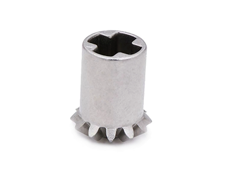
The main MIM advantage is producing small complex metal parts repeatedly with less machining on molded features. MIM can be valuable when the part includes small holes, ribs, gear teeth, splines, thin sections, internal forms, undercuts, logos, or other details that would take many CNC operations to reproduce.
MIM also supports a broad material route when the required alloy is available as powder feedstock. Buyers can review MIM materials such as stainless steel, low alloy steel, tool steel, titanium alloy, tungsten alloy, and cobalt alloy for corrosion resistance, hardness, wear resistance, magnetic response, density, or high-temperature requirements. Final material selection remains subject to buyer specification, powder availability, and qualification needs.
MIM can reduce material removal compared with machining from bar stock because the molded shape is closer to the final geometry. This does not mean every feature is finished after sintering. Datum faces, bearing seats, threaded holes, sealing surfaces, or cosmetic surfaces may still need CNC machining, polishing, heat treatment, passivation, coating, or inspection after sintering.
MIM Limitations: Tooling Cost, Shrinkage, Size, and Process Control
MIM limitations come from tooling investment, material availability, part size, shrinkage, and multi-stage process control. MIM tooling must compensate for sintering shrinkage, so design changes after tooling approval can be costly. For early prototypes, CNC machining prototyping or 3D printing prototyping may be more practical before committing to MIM tooling.
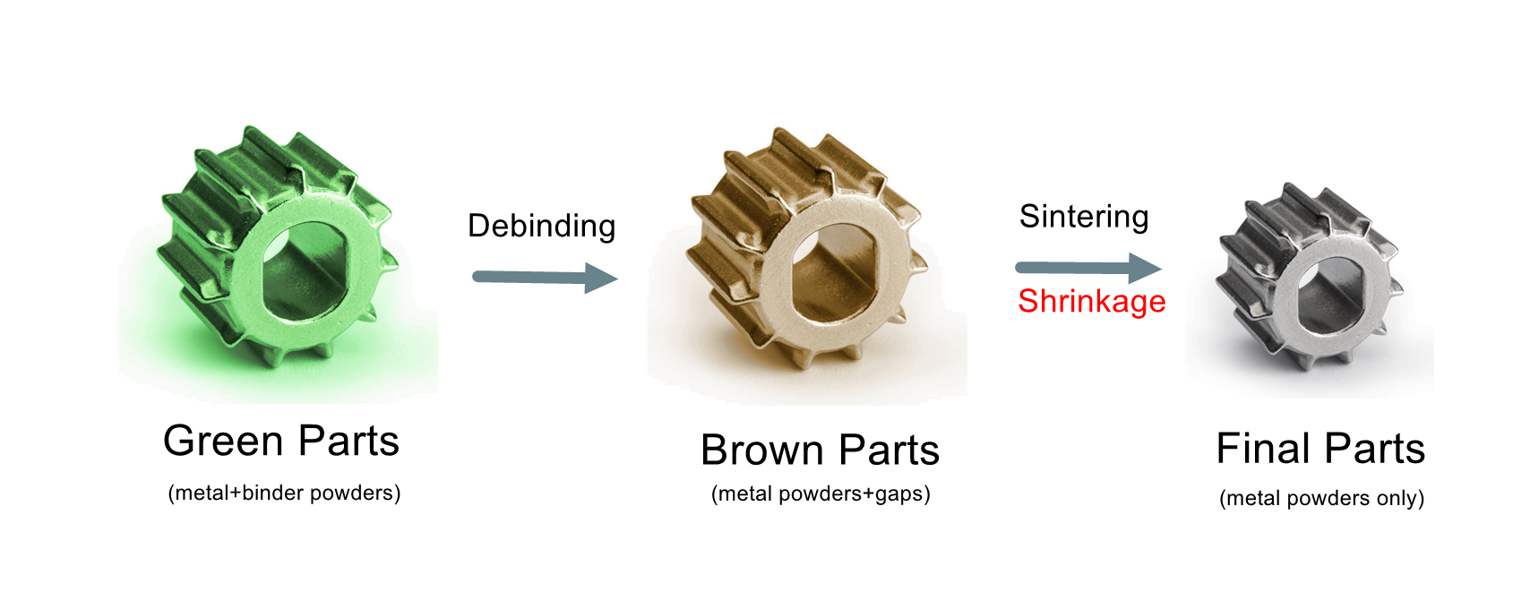
Sintering shrinkage is a central MIM risk. Shrinkage behavior depends on material, powder loading, part wall thickness, geometry balance, support method, and sintering conditions. Buyers should not assume every molded feature will hold the same tolerance after sintering. Critical features should be marked on the drawing and matched with inspection evidence such as CMM reports, dimensional reports, go/no-go gauges, density checks, hardness tests, or visual acceptance standards.
Part size also matters. MIM is strongest for small complex components. Larger parts can be more difficult to debind, support, sinter uniformly, and inspect. When a part is large or has simple geometry, investment casting, die casting, powder pressing, stamping, or machining may be a better production route.
MIM Compared With CNC Machining and Investment Casting
MIM should be compared with other routes by geometry, quantity, material, tolerance, and secondary operations. CNC machining is often better for prototypes, low-volume parts, frequent design changes, large parts, or material testing from wrought stock. MIM is usually more attractive when the design is stable and the same small complex part will be produced repeatedly.
Investment casting may be better for larger castable metal parts, while MIM may be better for smaller parts with finer molded details. Die casting may fit non-ferrous housings or covers where the material and geometry match the die casting route. Route selection should not be based on process name alone; buyers should compare tooling cost, unit cost, material availability, machining allowance, finishing, inspection, and approval requirements.
When a previous cost table is unavailable, outdated, or not tied to the buyer's drawing, the safer approach is to quote from the real 3D model, drawing, material grade, quantity, and inspection package. This avoids making a cost decision from a generic example that may not represent the buyer's part.
MIM Production Considerations: Feedstock, Mold Design, Debinding, and Sintering
Successful MIM production depends on stable feedstock, mold design, debinding control, sintering control, and post-processing planning. Feedstock mixing must distribute metal powder and binder consistently. The mold must support filling, venting, gate location, ejection, and shrinkage compensation. MIM mold design should be reviewed before tooling when the part includes thin walls, undercuts, long flow paths, gear teeth, or tight cosmetic surfaces.
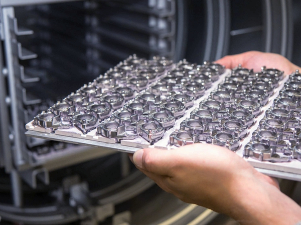
Debinding removes binder without damaging the part. Sintering bonds the metal particles and creates the final metal structure. Pressureless sintering is one common route, but the selected material and buyer specification may require a particular sintering atmosphere, heat treatment, or inspection plan. Post-processing can include CNC machining, polishing, heat treatment, passivation, PVD, coating, or assembly depending on the drawing.
Design and Inspection Information Needed Before MIM Tooling
A MIM review should define the part function, process risks, and acceptance evidence before tooling starts. Buyers should provide a 3D model, 2D drawing, material grade, expected annual quantity, prototype or production stage, critical dimensions, datum structure, surface finish, heat treatment, coating or plating requirement, inspection report requirement, and application environment.
For regulated or performance-critical applications such as medical, aerospace, automotive, or energy parts, the buyer should define qualification requirements, documentation, acceptance criteria, and final validation responsibilities. MIM parts may be considered for those applications when specifications and approvals are clear, but the article should not be read as a general qualification claim for any regulated industry.
Related FAQs