Mastering MIM Mold Design: 12 Key Considerations
This article explains MIM mold design for buyers developing custom metal injection molded parts, including small sintered metal brackets, slots, trays, gears, housings, clips, and precision mechanisms. The practical RFQ problem is deciding whether the part geometry, material feedstock, gate and runner layout, shrinkage allowance, debinding route, sintering support, ejection design, cavity strategy, secondary machining, and inspection evidence are clear enough before tooling is quoted.
The short answer is that MIM mold design must be planned around both injection molding and sintering. A mold can fill a green part successfully, but the final sintered part may still fail if shrinkage, wall thickness, gate location, ejection, distortion, or secondary machining are not considered. Buyers should mark critical dimensions, functional surfaces, and allowed design changes before requesting a MIM tooling quote.
Neway provides related metal injection molding support for custom sintered metal parts and MIM tooling reviews.
MIM Mold Design RFQ Decision for Custom Sintered Metal Parts
MIM mold design should start from the finished part requirement, not from the mold cavity alone. The supplier must understand the material grade, wall thickness, parting line, gate location, debinding path, sintering shrinkage, ejection marks, cosmetic surfaces, and secondary machining areas before recommending mold layout.
The manufacturing reason is that MIM feedstock behaves like a highly filled injection molding material during molding and like a powder metallurgy part during debinding and sintering. This dual behavior makes MIM mold design more sensitive to shrinkage and density control than conventional plastic injection molding.
MIM Mold Design Question | Engineering Reason | RFQ Input Needed |
|---|---|---|
Can the feedstock fill the part? | Metal powder loading changes flow, pressure loss, weld lines, and gate sensitivity | Material grade, wall thickness, flow length, thin sections, and visible surfaces |
Can the green part be ejected safely? | Green parts are fragile before debinding and sintering | Draft, ejector areas, ribs, bosses, undercuts, and allowed ejection marks |
Can shrinkage be controlled? | Debinding and sintering change size and can distort weak geometry | CTQ dimensions, datum strategy, sintering support, and post-machining allowance |
Can production stay consistent? | Cavity layout, temperature control, tooling wear, and maintenance affect repeatability | Annual volume, sample plan, inspection method, and maintenance expectations |
12 MIM Mold Design Considerations Buyers Should Review
The following design checks help buyers discuss MIM tooling with a supplier before mold steel is cut. Each item should connect to a drawing feature, a material requirement, or a production-stage decision.
Design Consideration | Why It Matters in MIM | Buyer Action Before RFQ |
|---|---|---|
Material feedstock | Powder size, binder, and metal loading affect flow and sintering | Confirm MIM material grade and allowed alternatives |
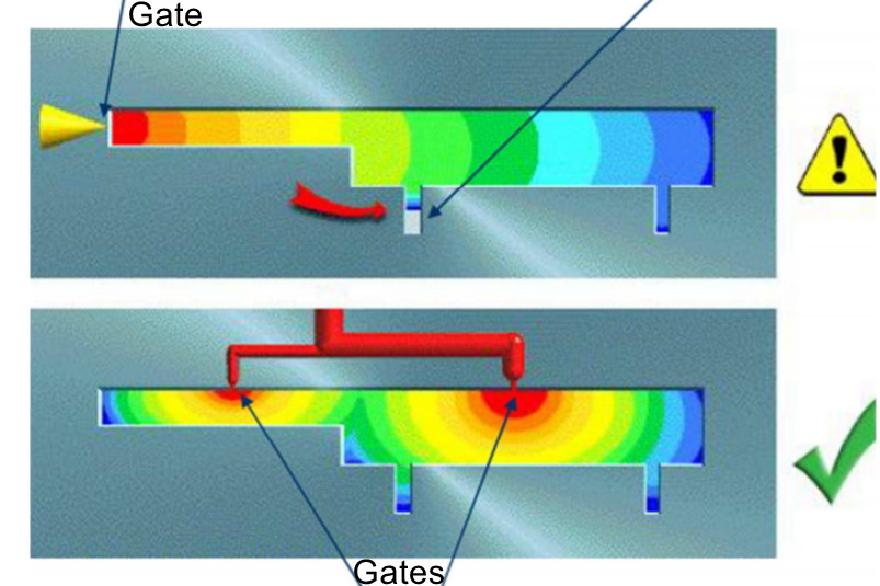
Gate location | Gate position affects filling, weld lines, cosmetic marks, and shrinkage balance | Mark visible surfaces and functional flow-sensitive features |
Runner layout | Runner balance affects cavity filling and pressure distribution | Share expected volume and whether multi-cavity tooling is needed |
Venting | Poor venting can trap gas and create defects in the molded green part | Identify thin sections, blind areas, and cosmetic surfaces |
Wall thickness | Thick-to-thin transitions can distort during debinding and sintering | Provide wall section map and allowed redesign areas |
Parting line | Parting line affects flash, witness marks, and secondary finishing | Define acceptable parting-line locations and cosmetic requirements |
Ejection design | Fragile green parts can crack or deform during ejection | Approve ejector locations and support features |
Undercuts | Slides or lifters can raise tooling complexity and green-part risk | Clarify whether undercuts can be redesigned or machined later |
Shrinkage allowance | Sintering shrinkage controls final size and dimensional repeatability | Mark CTQ dimensions, datums, and inspection method |
Sintering support | Weak spans and asymmetric parts may distort during sintering | Identify flatness, straightness, and support-sensitive features |
Cavity layout | Multi-cavity tools need balanced filling and consistent thermal behavior | Provide annual demand, sample plan, and cavity-count expectations |
Tool maintenance | Wear, vent blockage, and surface damage can affect production consistency | Ask how maintenance and inspection are planned for production tooling |
Gate, Runner, Material Flow, and Venting Design
Gate and runner design control how MIM feedstock fills the mold cavity. Feedstock contains metal powder and binder, so flow resistance, pressure, shear, and weld-line behavior differ from standard plastic molding. A gate placed for convenience may create cosmetic marks, weak flow fronts, unbalanced shrinkage, or debinding risk.
Venting is equally important. Trapped gas can create burn marks, incomplete filling, or weak areas in the green part. The mold should provide escape paths for gas without creating unacceptable flash or cosmetic defects.
The RFQ implication is that buyers should identify functional edges, visible faces, and surfaces that cannot accept gate vestige or weld-line risk. If the part will be polished, coated, or assembled against another component, those surfaces should be marked before mold design.
Part Geometry, Wall Thickness, Draft, Undercuts, and Ejection
MIM part geometry should allow stable molding and safe green-part handling. Thin ribs, small slots, sharp corners, blind holes, long unsupported spans, and abrupt wall transitions can affect filling, ejection, debinding, and sintering. The design may still be possible, but the tooling plan must address the risk.
Draft and ejection are often underestimated. A green MIM part is not as robust as a finished metal part, so the ejection system should support the part without damaging ribs, bosses, holes, or cosmetic surfaces. Undercuts may require slides, lifters, collapsible cores, or secondary machining, each with different cost and risk.
The buyer should provide the finished assembly function and the features that can change. If a slot, hole, or undercut can be modified for molding, the supplier can reduce tooling complexity before the mold is built.

Shrinkage, Debinding, Sintering, and Tolerance Planning
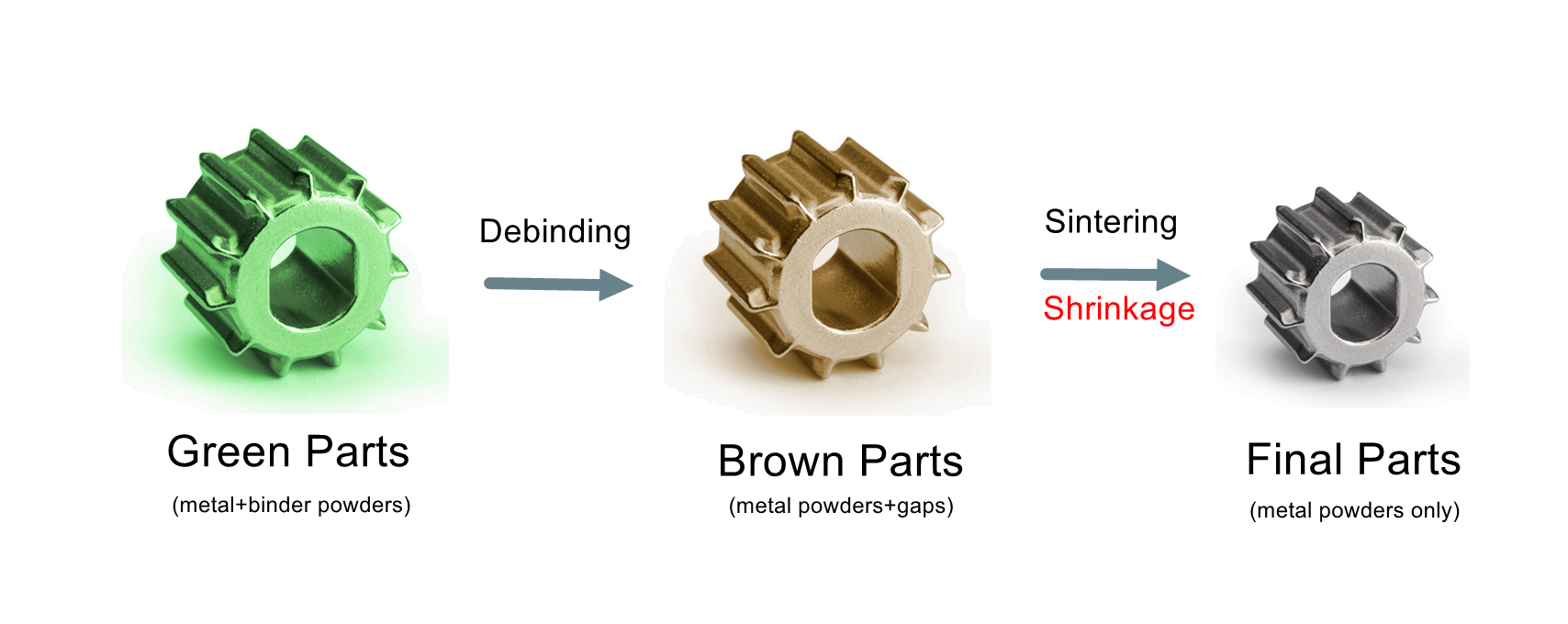
Shrinkage control is central to MIM mold design. The molded green part is larger than the final sintered part, and the tooling must account for predictable dimensional change. Material grade, feedstock, part geometry, wall thickness, debinding route, and sintering support all affect the final size.
Tolerance planning should separate as-sintered dimensions from dimensions that require machining, grinding, sizing, or other finishing. A bore, thread, sealing face, bearing surface, or assembly datum may need secondary machining even when most of the part is molded near net shape.
The RFQ implication is that buyers should mark CTQ dimensions and ask how shrinkage will be controlled and measured. The FAQ on tight-tolerance control during the MIM shrinkage process is a useful follow-up.
Mold Steel, Cavity Layout, Sensors, and Maintenance Choices
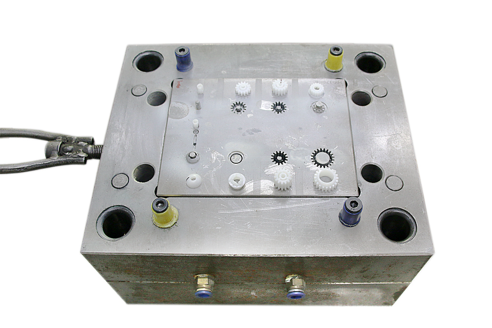
MIM mold material and cavity layout affect production consistency. Tool steel selection, surface treatment, polishing, vent design, cooling or heating control, and wear resistance should match the material feedstock and expected production demand.
Multi-cavity molds can improve output when volume supports them, but cavity balance becomes more important. If one cavity fills differently from another, dimensional variation and cosmetic defects can appear. Cavity pressure or temperature monitoring may be useful for selected production parts, but the need should be tied to part risk and quality evidence.
Maintenance planning should be discussed before production. Powder-filled feedstock can create wear and deposit buildup in gates, vents, runners, and cavity surfaces. Tool maintenance, cleaning intervals, and inspection evidence help control repeatability across batches.
Secondary Machining, Inspection, and Production Readiness
MIM mold design should include secondary operations from the start. Threads, precise bores, sealing faces, ground surfaces, polished areas, coatings, passivation, heat treatment, and assembly features may all affect tooling decisions and quotation.
Inspection should match the part's function. Common evidence can include dimensional reports, CMM checks, optical inspection, gauges, density checks, hardness checks, visual criteria, and functional assembly checks. For stainless steel MIM parts, material grade and heat treatment should also be connected to the final surface and corrosion requirements.
The manufacturing implication is that a MIM project is production-ready only when the mold design, sintering plan, finishing route, and inspection evidence support the same finished drawing.
RFQ Checklist for MIM Mold Design
A useful MIM mold design RFQ should help the supplier judge molding, debinding, sintering, secondary machining, and inspection before tooling begins. The buyer should provide the finished-part requirement and identify which features are flexible for manufacturing review.
RFQ Item | Why It Matters for MIM Tooling | Recommended Buyer Input |
|---|---|---|
Material grade | Feedstock, shrinkage, wear, sintering, and heat treatment depend on material | MIM grade, allowed alternatives, operating environment, and material evidence needed |
Geometry data | Gate, runner, venting, ejection, parting line, and shrinkage depend on full shape | STEP file, 2D drawing, revision, wall thickness, holes, slots, ribs, bosses, and datums |
Critical surfaces | Functional dimensions may require secondary machining or special inspection | CTQ dimensions, bores, threads, sealing faces, wear faces, visible surfaces, and gauges |
Tooling strategy | Cavity count, mold steel, temperature control, and maintenance affect consistency | Prototype quantity, annual volume, cavity expectation, sample plan, and production release schedule |
Post-processing | Heat treatment, machining, polishing, coating, and passivation change tooling assumptions | Finished-part drawing, surface finish, hardness, coating, cleaning, and assembly notes |
Inspection evidence | Acceptance depends on dimensional, material, surface, and functional checks | CMM report, visual criteria, density check, hardness check, functional test, and sampling plan |
Related FAQs
How Are Tight-Tolerance Components Controlled During the MIM Shrinkage Process?
Which Design Factors Affect Dimensional Accuracy in Precision MIM Parts?
Can Secondary Machining Improve Tolerances for Metal Injection Molded Components?
What Tooling Considerations Are Important for High-Volume MIM Production?
How Can Custom MIM Services Maintain Part Consistency Across Large Production Runs?
What Quality Inspection Methods Are Used for Tight-Tolerance MIM Components?