Mastering Rapid Prototyping: An Insider’s Guide to Multi Jet Fusion (MJF) 3D Printing
Multi Jet Fusion MJF 3D Printing RFQ Decision: Multi Jet Fusion (MJF) is a powder-bed additive manufacturing process that uses fusing agents, detailing agents, and thermal energy to build polymer prototype parts and limited functional parts. Buyers usually review MJF for nylon-like housings, brackets, clips, ducts, fixtures, lattice structures, and small batch plastic components. The practical RFQ problem is confirming whether MJF can meet the material behavior, surface finish, powder removal, dimensional control, post-processing, inspection, and validation requirements before prototype or bridge production orders.
MJF is useful when buyers need complex polymer geometry, repeatable prototype batches, and functional handling beyond basic visual models. MJF is not automatically a substitute for injection molding, CNC machining, SLS, FDM, or SLA. The correct route depends on part geometry, material requirement, load direction, cosmetic standard, tolerance expectation, quantity, and the decision the prototype must support.
What MJF 3D Printing Is for Rapid Prototyping
MJF is a powder-bed 3D printing process. A thin layer of polymer powder is spread across the build area, fusing and detailing agents are applied by an inkjet-style system, and thermal energy fuses the selected regions into a solid layer. The process repeats layer by layer until the part is complete.
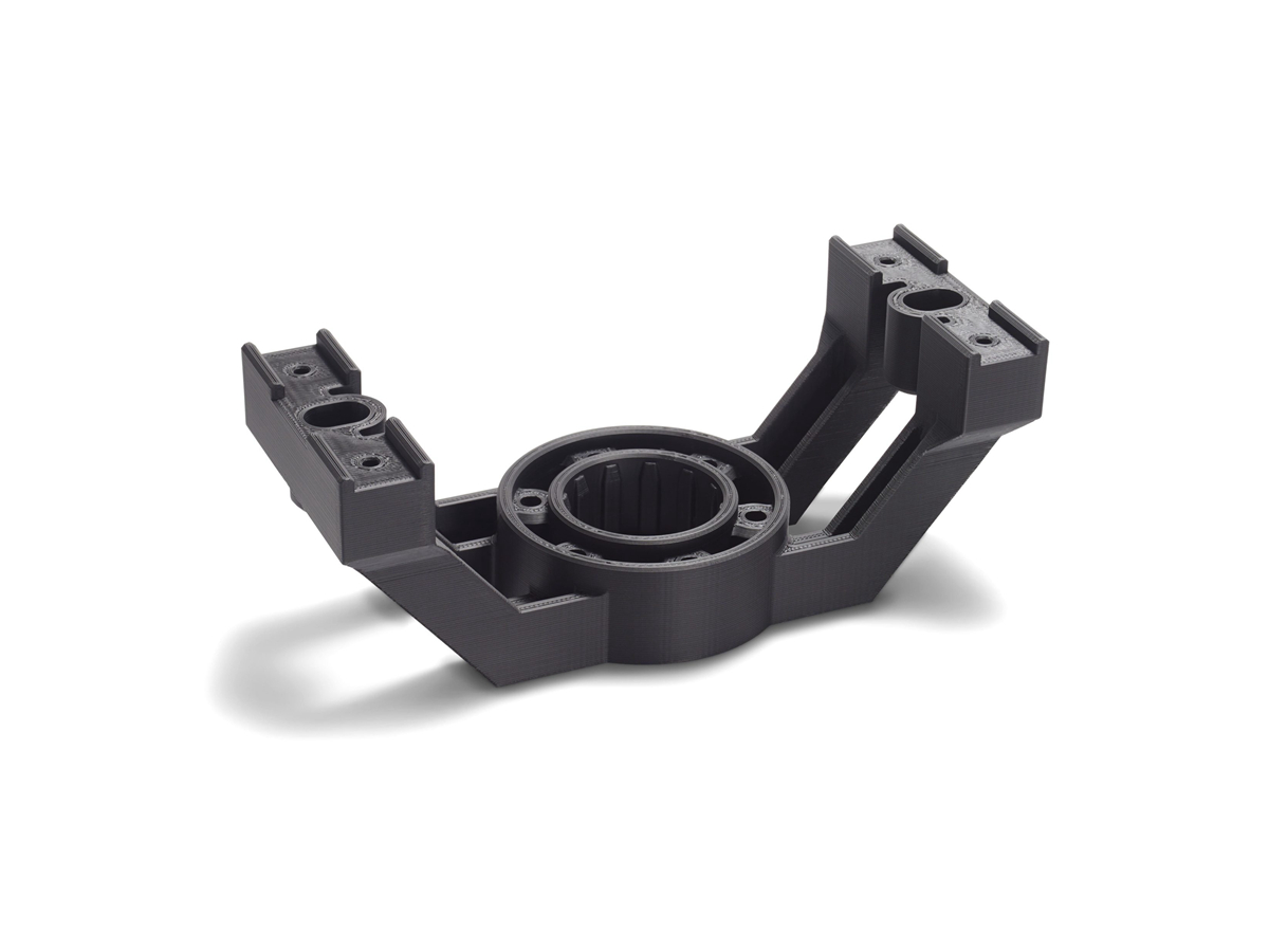
The buyer question is whether MJF supports the prototype purpose. MJF may fit functional prototypes, snap-fit trials, enclosure reviews, duct and bracket development, fixture testing, and low-volume design verification. If the buyer needs final production-equivalent material, cosmetic injection molded finish, transparent parts, metal strength, or certified product validation, another manufacturing route or additional testing may be needed.
How MJF Builds Powder Bed Prototype Parts
The MJF workflow starts with a 3D CAD model, process selection, powder material review, build orientation, nesting, agent application, thermal fusing, cooling, powder breakout, cleaning, and post-processing. Post-processing may include bead blasting, dyeing, smoothing, drilling, insert installation, assembly, or dimensional inspection.
Cooling and powder removal are important parts of the process. Thick sections, large flat surfaces, internal channels, and enclosed cavities can affect distortion and trapped powder risk. Buyers should define which cavities must be clear, which surfaces are cosmetic, and which dimensions are critical to assembly.
Which MJF Materials and Part Features Buyers Should Define
MJF material selection should be connected to the prototype's function. Buyers may need stiffness, impact behavior, flexibility, heat exposure, wear resistance, color, or surface texture. PA-type powder materials are often discussed in MJF projects, but the actual material option should be confirmed during quotation against the drawing and functional requirement.
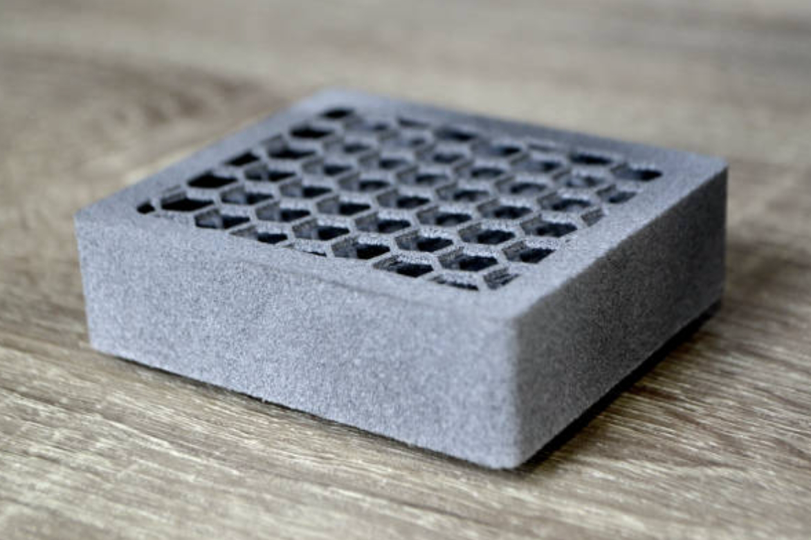
Part features matter as much as the material. Snap fits, clips, thin walls, living-hinge-like details, screw bosses, insert locations, internal ducts, lattices, and sealing surfaces should be identified before quotation. A feature that looks printable in CAD may still need review for powder escape, wall thickness, edge strength, and inspection access.
How MJF Compares With SLS, FDM, SLA, and CNC Prototypes
MJF is often compared with SLS 3D printing, FDM 3D printing, SLA 3D printing, and CNC machining. SLS and MJF are both powder-bed polymer routes, but machine strategy, available materials, surface texture, color options, build economics, and post-processing may differ. FDM is often used for quick thermoplastic prototypes. SLA is often used for fine visual detail. CNC machining may be better when the buyer needs a prototype from a solid engineering material.
The process choice should follow the buyer's decision. For appearance review, SLA may be more suitable. For quick form-and-fit iteration, FDM may be enough. For complex nylon-like functional prototypes or nested batch builds, MJF or SLS may be reviewed. For metal part validation, SLM or DMLS 3D printing may be a separate discussion.
What Surface Finish, Accuracy, and Post-Processing Affect
MJF parts usually have a powder-bed surface texture. That texture may be acceptable for internal prototypes, fixtures, and functional checks, but it may not match an injection molded cosmetic finish. Dyeing, smoothing, coating, or machining may be considered when the buyer needs a specific appearance or mating surface.
Dimensional accuracy depends on geometry, orientation, material, cooling, post-processing, and feature size. Small holes, long flat walls, large thin panels, snap clips, and mating datums should be identified on the drawing. If a hole, thread, flatness zone, or sealing surface is critical, the RFQ should state whether post-machining, insert installation, or inspection is required.
MJF Buyer Requirement | Manufacturing Risk | RFQ Detail Needed | Review Evidence |
|---|---|---|---|
Snap fit or clip | Breakage, weak engagement, or layer-related stress concentration. | Load direction, mating part data, cycle expectation, and material requirement. | Assembly fit check and buyer-defined functional test if required. |
Internal duct or enclosed cavity | Trapped powder, blocked passage, or difficult cleaning. | Powder escape openings, airflow or fluid need, and cleaning requirement. | Powder removal review and functional check if required. |
Cosmetic outer housing | Powder texture, color variation, or visible finishing marks. | Cosmetic side, color target, smoothing or coating expectation. | Visual standard and surface finish review. |
Precision hole or insert boss | Hole variation, rough wall, weak insert retention, or fit mismatch. | Thread or insert type, datum scheme, and inspection method. | Gauge check, dimensional report, or post-machining review. |
What Inspection and Validation Buyers Should Define
Inspection for MJF parts should match the prototype decision. A concept prototype may need visual review and key dimensions. A fixture may need hole position and assembly fit. A functional prototype may need dimensional inspection, material confirmation, repeated-use testing, heat exposure testing, or load testing defined by the buyer.
Buyers should not assume that an MJF prototype automatically represents the final manufacturing route. If the final part will be injection molded, machined, cast, or metal printed, the MJF prototype should be treated as evidence for geometry and function only where the buyer's validation plan allows it.
What Neway Precision Reviews for MJF Prototype Parts
Neway Precision reviews MJF prototype RFQs by checking the CAD model, part size, material requirement, wall thickness, internal channels, trapped powder risk, snap features, mating surfaces, build orientation, surface finish, post-processing, dimensional inspection, and functional test scope. The review also considers whether 3D printing prototyping, SLS, FDM, SLA, CNC machining, rapid molding, or another route better supports the buyer's next decision.
A complete RFQ should include the 3D model, drawing if critical dimensions exist, material expectation, prototype purpose, quantity, surface finish, color requirement, powder removal concerns, mating parts, post-processing requirements, and requested inspection evidence. Final product validation remains the buyer's responsibility.
Related FAQs