What Is FDM 3D Printing?: Revolutionizing Prototyping & Manufacturing
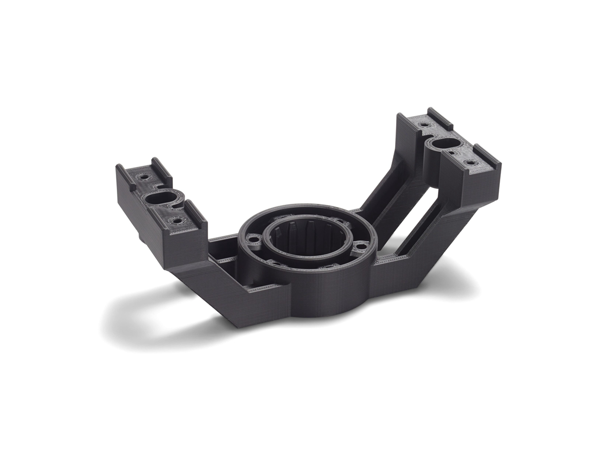
FDM 3D Printing RFQ Decision: Fused Deposition Modeling (FDM) is an additive manufacturing process that extrudes thermoplastic filament through a heated nozzle and builds prototype parts layer by layer. This article explains how buyers should evaluate FDM for plastic housings, fixtures, fit-check models, jigs, concept prototypes, and limited functional prototypes. The practical RFQ problem is deciding whether FDM can meet the required material behavior, part strength, surface finish, dimensional control, layer orientation, support removal, and validation plan before ordering prototype parts.
FDM is useful when the buyer needs fast design feedback, low tooling commitment, and a physical plastic part for geometry review. FDM is not automatically suitable for every production or load-bearing application. Buyers should define the part purpose, material preference, functional surfaces, build orientation concerns, post-processing needs, and inspection expectations so the prototype supplier can review the process risk.
What FDM 3D Printing Is
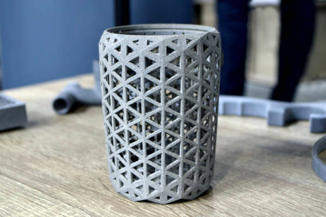
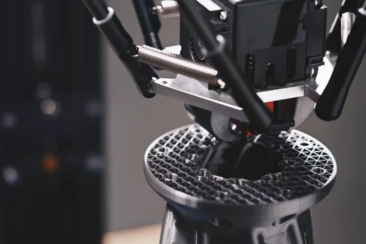
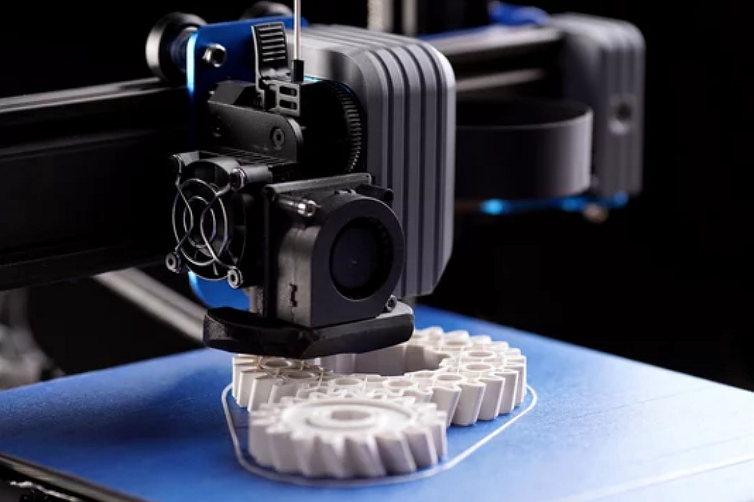
FDM 3D printing is a material-extrusion process. A thermoplastic filament is fed into a heated nozzle, softened, deposited onto a build platform, and stacked into a three-dimensional part from CAD data. The part is created by layer height, toolpath, shell thickness, infill pattern, raster direction, and support structure decisions.
The buyer question is whether this layer-by-layer thermoplastic process fits the part function. FDM can be practical for form and fit prototypes, assembly checks, ergonomic models, fixture concepts, packaging checks, and some engineering prototypes. If the buyer needs tight tolerance, smooth cosmetic finish, isotropic strength, thin polished walls, transparent optics, or production material equivalence, another process may need review.
How FDM Builds Thermoplastic Prototype Parts
The FDM workflow starts with a 3D CAD model, file preparation, slicing, material selection, build orientation, support generation, printing, support removal, and post-processing. Post-processing may include sanding, drilling, tapping, insert installation, bonding, vapor smoothing where suitable, painting, or dimensional inspection.
Build orientation affects surface quality and strength direction. A layer line that is acceptable on a visual prototype may be a weak direction on a snap-fit tab, hinge, bracket, or loaded boss. Support material can affect underside surfaces and small details. Buyers should identify which surfaces are cosmetic, which surfaces contact mating parts, and which features carry load during testing.
Which FDM Materials and Part Features Buyers Should Define
FDM material selection should start with the prototype requirement. ABS is often reviewed for general plastic prototypes. Polycarbonate PC may be reviewed when the buyer needs higher heat or impact-related performance than common model plastics. PET and TPU may be reviewed for different flexibility, durability, or handling requirements.
The RFQ should not simply say "3D print this part." Buyers should provide the CAD file, target material, prototype purpose, quantity, critical dimensions, thread requirements, inserts, surface finish, color if relevant, assembly conditions, and any functional test. When the material is not final, the RFQ should state whether the FDM part is for visual review, fit check, load test preparation, fixture use, or manufacturability discussion.
Where FDM Fits in Prototype and Manufacturing Decisions
FDM is usually strongest as an early prototype process, not as a universal replacement for injection molding, CNC machining, casting, or metal additive manufacturing. FDM can help buyers check size, shape, connector clearance, housing layout, hand feel, bracket access, and fixture concepts before committing to tooling or metal production routes.
For custom parts, FDM may be compared with SLA, SLS, MJF, CNC machining, and rapid tooling. SLA may be reviewed for smoother surfaces or fine details. SLS and MJF may be reviewed for nylon-like functional prototypes. CNC machining may be reviewed when the prototype must be made from a production-intent solid material. The right route depends on part geometry, material requirement, quantity, surface finish, lead time, and validation purpose.
What FDM Limitations Affect Strength, Accuracy, and Surface Finish
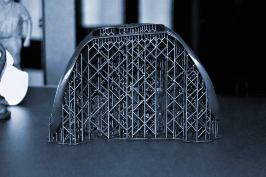
FDM limitations usually come from layer bonding, material shrinkage, nozzle path, support removal, and thermoplastic behavior. Common risks include visible layer lines, anisotropic strength, warpage, stringing, poor overhang surfaces, rough support contact areas, loose holes, weak thin pins, and dimensional variation in tall or thin parts.
These limitations should be treated as RFQ information, not surprises after printing. If a prototype has screw bosses, snap fits, clips, living hinges, sealing faces, thin walls, or heat exposure, the buyer should identify those features before quotation. The supplier can then review build orientation, wall thickness, infill, post-machining, inserts, or another process route.
FDM Part Feature | Manufacturing Risk | RFQ Detail Needed | Review Evidence |
|---|---|---|---|
Snap-fit tab or clip | Layer separation, brittle failure, or inaccurate engagement. | Load direction, mating part data, material preference, and test purpose. | Build orientation review and functional fit check. |
Large flat housing wall | Warping, layer marks, and cosmetic variation. | Cosmetic surface, wall thickness, color, and post-processing expectation. | Visual inspection and dimensional check. |
Threaded hole or insert boss | Weak thread, poor insert retention, or hole-size variation. | Thread standard, insert type, torque-related buyer test, and mating hardware. | Thread gauge or assembly fit check when required. |
Support-heavy overhang | Rough underside surface, support scars, or broken small features. | Acceptable surface side, support access, and post-processing limit. | Orientation review and surface inspection. |
How Buyers Can Prepare FDM Files for Quotation
A useful FDM RFQ includes a clean 3D model, drawing if critical dimensions exist, material preference, prototype purpose, quantity, required color, surface finish, inserts or fasteners, mating parts, inspection needs, and any functional test. If the buyer is comparing FDM with SLA, SLS, MJF, CNC machining, or injection molding, the RFQ should state the decision criteria.
Buyers should also identify what can change. If wall thickness, ribs, hole diameter, boss shape, fillet radius, or orientation can be adjusted, the supplier can suggest manufacturability changes. If the prototype must match a released design exactly, the supplier can evaluate print risk and possible post-processing without assuming design changes.
What Neway Precision Reviews for FDM Prototype Parts
Neway Precision reviews FDM prototype RFQs by checking the CAD model, part size, material requirement, wall thickness, thin features, snap fits, holes, threads, surface finish, support access, build orientation, dimensional inspection needs, and functional testing scope. The review also considers whether 3D printing prototyping, CNC machining, rapid molding, or another manufacturing route better supports the buyer's next decision.
A complete RFQ should make the prototype decision clear: visual model, assembly fit check, functional prototype, fixture, or bridge part. The buyer remains responsible for final product validation, especially when the part is used for load-bearing, heat exposure, electrical contact, regulated testing, or safety-related evaluation.
Related FAQs