3D Printing: A Comprehensive Guide to Process, Classification, and Applications
This article explains the 3D printing process, additive manufacturing classifications, material choices, and prototype part decisions that affect RFQs for custom metal and plastic parts. Buyers comparing FDM, SLA, SLS, DLP, MJF, DMLS, SLM, and PolyJet should define part function, material, tolerance needs, surface finish, inspection requirements, and whether the printed part is for visual review, functional testing, or production-route validation.

3D Printing Process and RFQ Decision
3D printing is an additive manufacturing route that builds a part layer by layer from a digital model. The buyer decision is not simply whether a part can be printed. The real RFQ question is which printing route, material, post-processing sequence, and inspection plan can produce a prototype or low-volume component that answers the engineering question.
For a visual model, dimensional accuracy and functional material strength may be secondary to appearance. For a functional prototype, the print route must support load, heat, assembly, thread inserts, sealing, or wear review. For metal prototypes, the buyer may need to compare metal 3D printing with CNC machining prototyping, precision casting, or rapid tooling before committing to production.
Before quotation, buyers should define part size, target material, production stage, critical dimensions, cosmetic surfaces, surface roughness, heat or chemical exposure, assembly requirements, post-processing needs, and inspection evidence. These details prevent a printing quote from assuming the wrong technology or the wrong acceptance level.
How Additive Manufacturing Builds Parts From CAD Files
The 3D printing workflow starts with a CAD file or mesh model. The model is checked for wall thickness, closed surfaces, support needs, build orientation, and features that may fail during printing or post-processing. Slicing software then divides the model into layers and creates machine instructions for extrusion, photopolymer curing, powder fusion, or metal laser melting.
Build orientation affects support marks, anisotropic strength, surface quality, dimensional variation, and cost. A part printed flat may reduce support material, while a part printed upright may improve some surfaces or internal features. Buyers should identify datum surfaces and critical faces so the supplier can orient the part around inspection needs, not only build convenience.
After printing, many parts need support removal, depowdering, curing, heat treatment, stress relief, machining, polishing, blasting, dyeing, coating, thread inserts, or assembly. Post-processing can be as important as the print itself, especially for functional prototypes, metal parts, and parts that must fit into an assembly.
FDM, SLA, SLS, DLP, MJF, DMLS, SLM, and PolyJet Route Selection
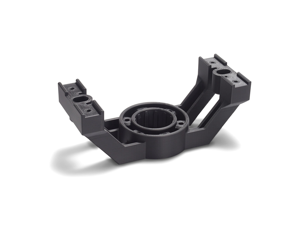
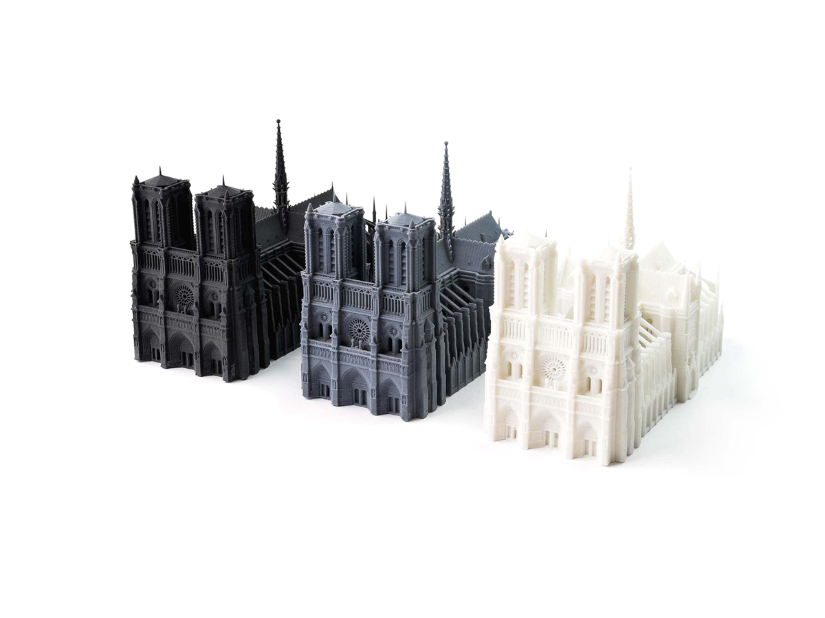
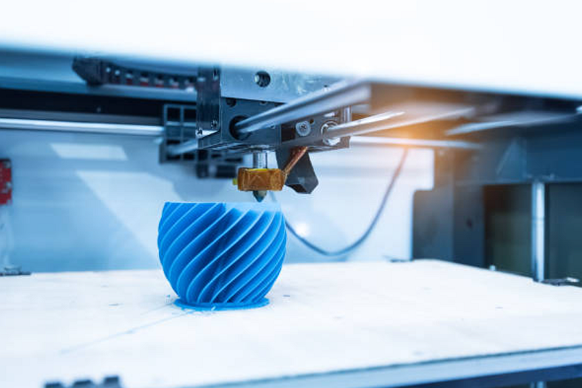
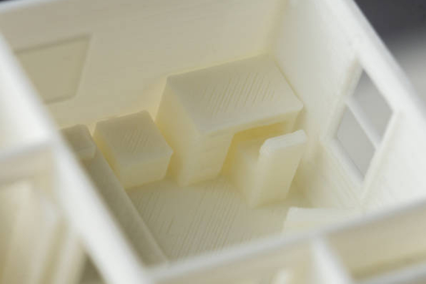
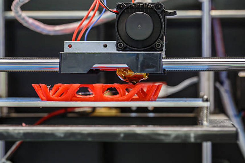
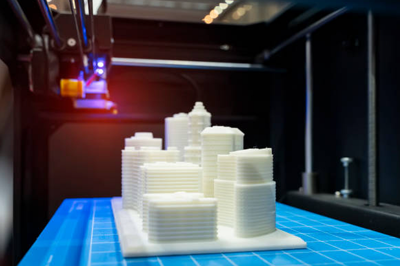
Each 3D printing classification solves a different manufacturing problem. FDM extrudes thermoplastic filament and is often useful for concept models, fixtures, and larger low-cost prototypes. SLA and DLP use photopolymer curing and are often reviewed for smooth surfaces or fine detail. SLS and MJF use polymer powder bed fusion and can support more complex functional plastic prototypes without the same support structure approach as FDM or SLA.
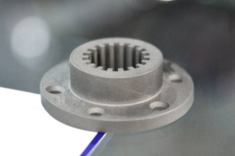
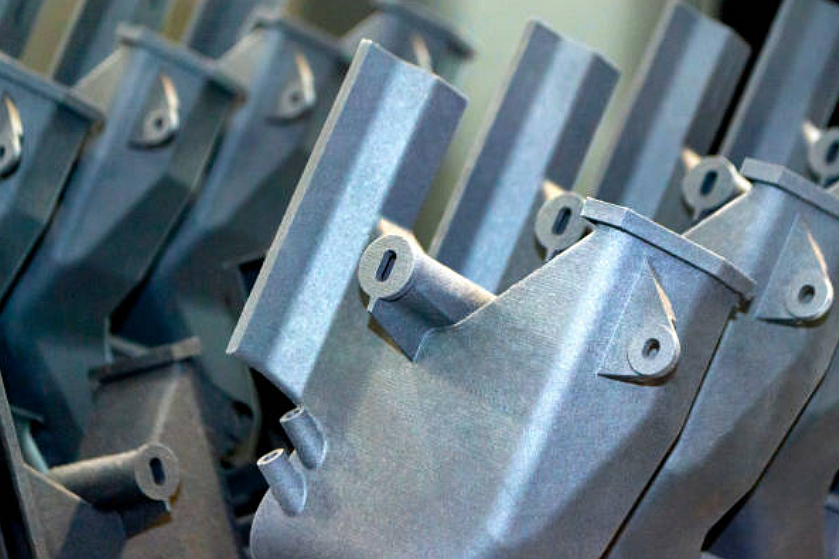
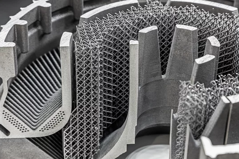
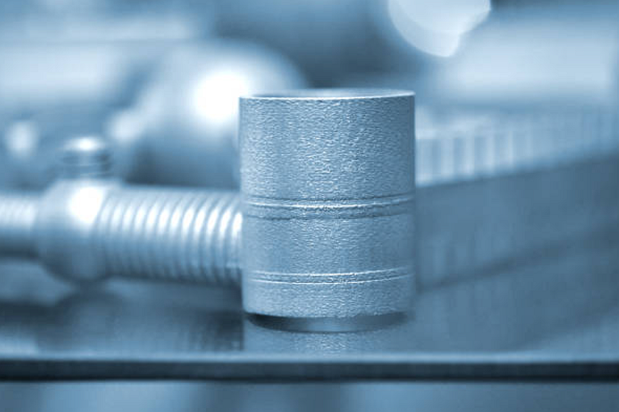
Metal 3D printing routes such as DMLS and SLM use metal powder and laser energy to build dense metal parts. Metal printing may need support removal, stress relief, heat treatment, CNC machining, surface finishing, and inspection before a prototype can be evaluated as a functional part.
3D Printing Route | Typical Part Review | Main Manufacturing Risk | Buyer Confirmation Needed |
|---|---|---|---|
FDM | Concept models, fixtures, larger thermoplastic prototypes | Layer lines, anisotropic strength, surface finish limits | Material, load direction, cosmetic expectations |
SLA or DLP | Fine detail, smooth surfaces, visual or fit-check prototypes | Resin brittleness, UV sensitivity, support marks | Detail needs, surface quality, functional exposure |
SLS or MJF | Functional polymer prototypes and complex nylon parts | Powder surface texture, shrink variation, sealing limits | Assembly fit, dyeing, sealing, dimensional checks |
DMLS or SLM | Metal prototypes with complex channels or lightweight geometry | Residual stress, support removal, rough surfaces, distortion | Heat treatment, machining allowance, inspection plan |
PolyJet | Visual models, multi-material appearance, ergonomic review | Material durability limits and surface aging | Visual objective, color, hardness, review environment |
3D Printing Materials for Plastic, Metal, Composite, and Ceramic Prototypes
3D printing materials should be selected around the test question. ABS, PC, PET, TPU, nylon, photopolymer resin, and filled polymers each have different stiffness, heat resistance, impact response, surface quality, and post-processing behavior. A resin chosen for appearance may not represent production thermoplastic performance.
Metal materials for additive manufacturing may include aluminum alloys, stainless steels, nickel alloys, cobalt alloys, and selected superalloys. Material selection should consider powder availability, printability, heat treatment, machining allowance, corrosion or heat exposure, and the inspection evidence needed by the buyer.
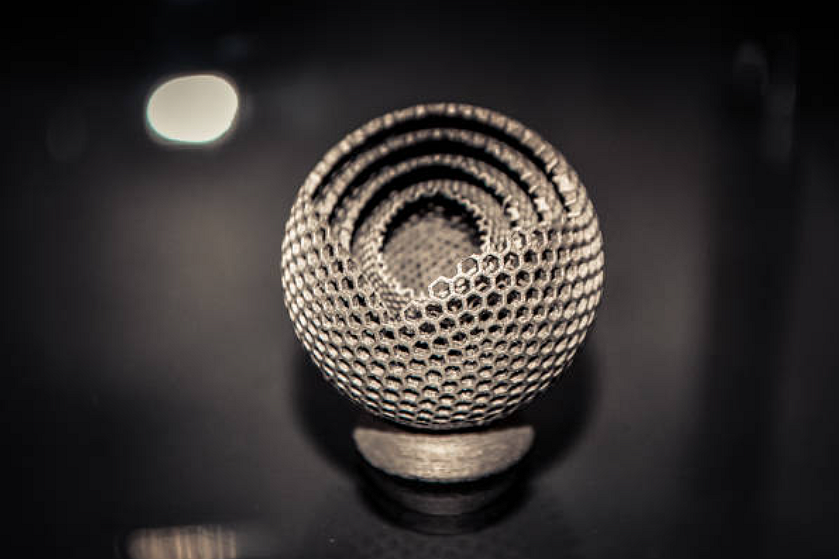
Ceramic and composite 3D printing can support special thermal, insulation, wear, or stiffness requirements, but route selection must be reviewed carefully. If a prototype is intended to represent a molded, cast, machined, or sintered production part, the buyer should confirm which properties are being tested and which properties are only approximate.
What 3D Printing Can and Cannot Prove Before Production Tooling
3D printing is strong for fast design iteration, shape review, assembly checks, ergonomic evaluation, internal channel review, and early functional testing. It can reduce development risk before CNC machining, casting, injection molding, die casting, or production tooling. However, a printed prototype does not automatically prove production material behavior, mold shrinkage, casting porosity, die-casting flow, or long-term fatigue performance.
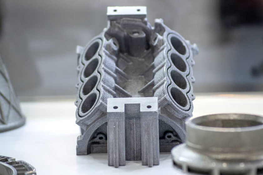
For plastic parts that will later move to plastic injection molding, the buyer should remember that printed layer behavior differs from molded resin flow, weld lines, gate marks, and molded shrinkage. For metal parts that will later move to casting, machining, or metal injection molding, the buyer should separate prototype fit validation from production process qualification.
Inspection, Post-Processing, and Defect Risks in 3D Printed Parts
3D printed parts can have defects related to layer bonding, warpage, porosity, rough surfaces, support scars, powder residue, resin cure variation, trapped material, or dimensional drift. The defect risk depends on the print route, material, orientation, wall thickness, support strategy, machine settings, and post-processing sequence.
Inspection should match the prototype purpose. Visual models may need appearance and basic dimensional checks. Functional prototypes may need CMM inspection, dimensional reports, surface roughness review, assembly checks, thread inspection, leak testing, pressure testing, or hardness and heat-treatment records for metal parts. Buyers should state which evidence is required at RFQ stage because inspection scope changes cost and schedule.
Post-processing should also be defined early. Support removal, sanding, blasting, polishing, dyeing, painting, coating, machining, heat treatment, stress relief, and insert installation can change dimensions and surface conditions. If a printed part needs post-machined datums or sealing faces, the quote should include machining allowance and inspection after finishing.
When CNC Machining, Casting, Rapid Molding, or Injection Molding May Be Better
3D printing is not the best route for every prototype or low-volume part. CNC machining may be better when the buyer needs production-like material, tight machined datums, threaded metal features, or smoother machined surfaces. Rapid molding prototyping may be better when the buyer needs molded thermoplastic behavior before production tooling. Casting or die casting may be better when the prototype must represent a later cast route.
The best prototype route depends on the decision the buyer wants to make. If the question is appearance, a resin print may be enough. If the question is assembly fit, SLS, MJF, CNC machining, or printed metal may be better. If the question is production cost, the buyer should compare prototype cost with the cost of tooling, machining, molding, casting, inspection, and later engineering changes.
Buyer RFQ Checklist for 3D Printing Prototyping
A useful 3D printing RFQ should include the CAD file, drawing, material preference, prototype purpose, target quantity, critical dimensions, surface finish, color, post-processing needs, assembly interfaces, threaded features, heat or chemical exposure, and inspection requirements. If the prototype must support production-route decisions, the RFQ should also state the planned production process.
For metal 3D printing, buyers should identify heat treatment, stress relief, machining allowance, support removal limits, surface finish, and non-destructive inspection requirements where applicable. For polymer printing, buyers should identify whether the part is for visual review, fit check, functional load testing, sealing, or environmental exposure.
Clear RFQ data allows the supplier to recommend a print route, material, orientation, support strategy, finishing plan, and inspection method. It also helps the buyer avoid a common mistake: selecting a low-cost print that answers the wrong engineering question.
Related FAQs