How do we deal with the undercut in injection molding?
How should undercuts be handled in injection molding?
Undercuts in injection molding should be handled by first reviewing whether the part geometry can be changed, then deciding whether slides, lifters, side cores, collapsible cores, unscrewing mechanisms, insert molding, or secondary operations are justified. The practical RFQ problem is choosing the undercut solution that allows reliable molding and ejection without adding avoidable tooling cost, tolerance risk, cosmetic marks, or production maintenance.
An undercut is a feature that prevents a molded part from releasing straight from the mold in the normal opening direction. Undercuts may appear as hooks, snap features, side holes, internal threads, grooves, clips, locking tabs, cable openings, or hidden side details. Plastic injection molding, metal injection molding, and ceramic injection molding can all face undercut problems, but the solution depends on material behavior, part size, shrinkage, feature strength, and production quantity.
When should the part design be changed to remove undercuts?
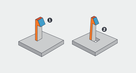
Design change is usually the first option when the undercut is not essential to the part function. Adding draft, moving the parting line, opening a side window, splitting the component into two pieces, changing a snap detail, or replacing a hidden hook with a simpler fastening feature can reduce mold complexity. This approach can lower tooling risk and make production more repeatable.
The buyer should identify which undercut features are functional and which are only inherited from an early design. A cosmetic groove, unnecessary reverse wall, or overly aggressive snap may be easier to redesign than to mold with side action. If the undercut is needed for assembly, sealing, retention, or product function, the RFQ should explain the purpose so the tooling review can choose an appropriate mechanism.
When are slides, lifters, and side cores used for undercuts?
Slides, lifters, and side cores are common tooling solutions for external side holes, clips, windows, latch features, and side-facing geometry. A slide moves sideways before the part is ejected. A lifter moves at an angle to release a feature. A side core forms a hole, recess, or feature that cannot be created in the main mold opening direction.
These mechanisms add cost, mold size, wear points, timing requirements, and maintenance. They can also leave parting lines, witness marks, or small mismatch areas. The RFQ should define cosmetic surfaces, sealing surfaces, critical dimensions near the side action, expected production volume, and whether the side-action feature needs inspection with CMM, pin gauges, or go/no-go gauges.
When are collapsible cores and unscrewing molds needed?
Collapsible cores can help mold internal undercuts such as internal grooves, snap rings, or features that wrap around the core. Unscrewing molds are used when molded threads or helical features must be released without damaging the part. These mechanisms are more complex than simple slides and should be justified by the part function and production plan.
For threaded features, the buyer should confirm whether a molded thread is truly needed or whether a post-molded tapped insert, metal insert, secondary tapping, or assembly change is more practical. The correct decision depends on material, thread strength, wear requirement, torque requirement, tolerance, and the number of parts to be produced.
Can insert molding or overmolding solve undercut problems?
Insert molding can sometimes replace a difficult molded undercut with a metal insert, threaded insert, bushing, pin, or reinforcement. Overmolding can create grip, seal, cushion, or retention features using a second material when the design and material compatibility support that route. These options may simplify the primary mold, but they introduce insert placement, bonding, flash, and assembly-control questions.
The RFQ should include the insert drawing, insert material, overmold material, bonding requirement, pull-out requirement, torque requirement, and any leak or durability test. Insert molding and overmolding should solve a functional problem, not only move complexity from one process step to another.
When are secondary operations or route changes better?
Secondary operations may be better when the undercut is small, low volume, difficult to tool, or located on a precision surface. Drilling, milling, trimming, tapping, slotting, or manual removal can be considered after molding when tooling complexity is not justified. For MIM and CIM parts, post-sintering machining or grinding may be needed for some undercut-like features, but the hardness and brittleness of the material must be considered.
A route change may be better when the part has too many undercuts for reliable injection molding. CNC machining, casting, additive manufacturing, fabrication, or assembly from multiple parts may be reviewed depending on quantity, material, tolerance, and cost target. Buyers should request a process-route review when the undercut controls the cost or manufacturability of the whole part.
What RFQ information helps review undercuts?
A useful RFQ should include the 2D drawing, 3D model, material grade, production quantity, undercut function, assembly requirement, cosmetic surfaces, critical dimensions, draft limits, tolerance requirements, and inspection method. If an undercut is tied to snap fit, sealing, cable routing, fluid flow, threaded assembly, or retention force, the buyer should describe that functional requirement.
The mold review should identify which undercuts can be removed by design, which require side action, which require special core mechanisms, and which may be better handled after molding. This classification helps the buyer compare tooling cost, production risk, cycle time, maintenance, and final inspection before committing to the mold design.
Undercut Solution | Best-Fit Situation | Manufacturing Risk | Buyer Confirmation Needed |
Design change | Nonfunctional undercuts, avoidable reverse walls, or features that can be split or drafted | Assembly change, appearance change, or need for buyer design approval | Functional purpose, draft allowance, parting line preference, and cosmetic surface limits |
Slide, lifter, or side core | Side holes, side clips, latch details, and features outside the main mold opening direction | Tool wear, mismatch, flash, cycle time, and side-action maintenance | Critical dimensions, surface class, expected volume, and inspection method |
Collapsible core or unscrewing mold | Internal undercuts, threaded features, or geometry wrapped around a core | Higher tooling complexity, mechanism timing, thread damage, and maintenance cost | Thread function, torque requirement, material behavior, and production quantity |
Secondary operation or route change | Low volume, difficult-to-tool features, or undercuts that need post-mold precision | Added operation cost, fixture requirement, burrs, dimensional variation, and handling damage | Quantity, tolerance, datum structure, burr allowance, and final inspection evidence |
Related FAQs
What considerations are essential for designing parts for injection molding?
What features should be avoided in injection molding designs?
What design features should be avoided in rapid injection molding?
What is the difference between insert molding and overmolding?
Are there any limitations or challenges associated with overmolding?