Metal Injection Molding: When was Metal Injection Molding Invented
This article explains when metal injection molding was invented and why the MIM process matters for custom small metal parts today. Modern metal injection molding emerged in the 1970s by combining powder metallurgy with plastic injection molding principles, then moved toward commercial production in the 1980s. For RFQ review, the practical issue is how that history shaped feedstock, debinding, sintering shrinkage, material selection, and inspection control for complex metal components.
When Metal Injection Molding Was Invented and Commercialized
Metal injection molding was not created as a single isolated step. The modern MIM route developed when engineers combined fine metal powders, polymer binder systems, injection molding, debinding, and sintering into a repeatable process for small complex metal parts.
The key development period is generally described as the 1970s for the emergence of the modern MIM concept and the 1980s for wider commercialization. This timeline matters because MIM became practical only when powder control, binder formulation, molding equipment, debinding control, and sintering knowledge could work together.
Why Powder Metallurgy Needed Metal Injection Molding
Traditional powder metallurgy can form strong sintered metal parts, but pressing direction and tooling limits can restrict complex geometry. MIM extended powder metallurgy by using injection molding to form small three-dimensional features before debinding and sintering.
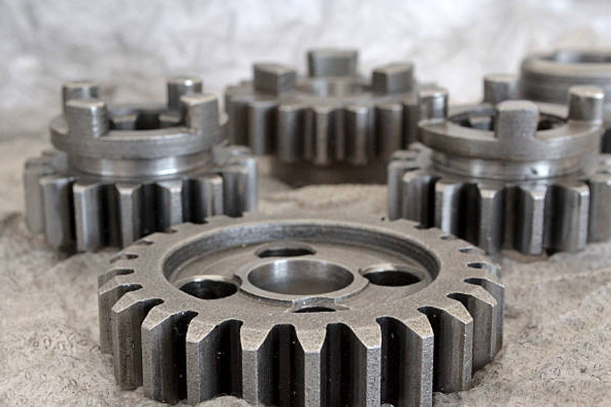
For buyers, the difference is practical. A pressed powder metal gear, a machined gear, and a MIM gear may all be metal parts, but the correct route depends on geometry, material grade, density requirement, annual quantity, heat treatment, and inspection evidence.
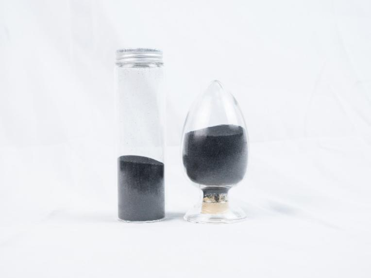
How Feedstock, Debinding, and Sintering Made MIM Practical
The invention of modern MIM depended on feedstock that could flow into a mold cavity while holding enough metal powder to sinter into a useful part. Binder systems made molding possible, but the binder had to be removed without cracking or distorting the component.
After debinding, sintering densifies the brown part and creates final metal properties. This step also creates shrinkage, so buyers should identify datum surfaces, critical holes, assembly surfaces, and any post-sinter machining before quotation.
What MIM Development Means for Modern Material Selection
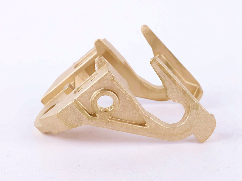
MIM material selection grew as powder manufacturing improved. Stainless steel, low-alloy steel, tool steel, tungsten alloy, copper alloy, titanium alloy, and specialty alloys may be reviewed when the powder route, debinding route, sintering route, and part geometry are suitable.
MIM Development Area | Manufacturing Meaning | Buyer RFQ Impact |
Powder size, shape, and chemistry affect feedstock flow and sintered properties. | Specify material grade, property requirement, and any material certificate expectation. | |
Binder and debinding route | Binder removal affects cracking, distortion, and part cleanliness before sintering. | Share geometry risks such as thick sections, small holes, and fragile features. |
Sintering controls shrinkage, density, dimensional stability, and final properties. | Define critical dimensions, datum scheme, machining allowance, and inspection plan. |
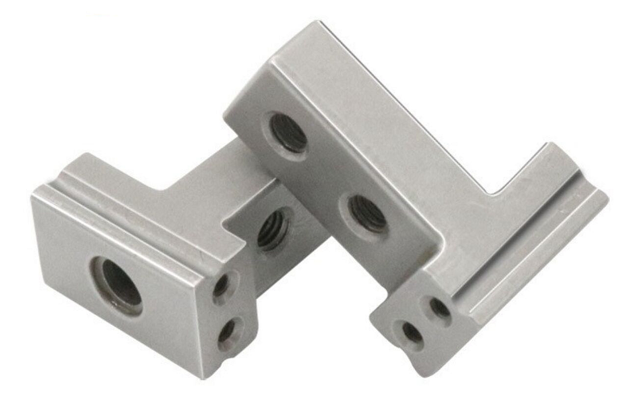
How MIM Applications Expanded Into Functional Metal Components
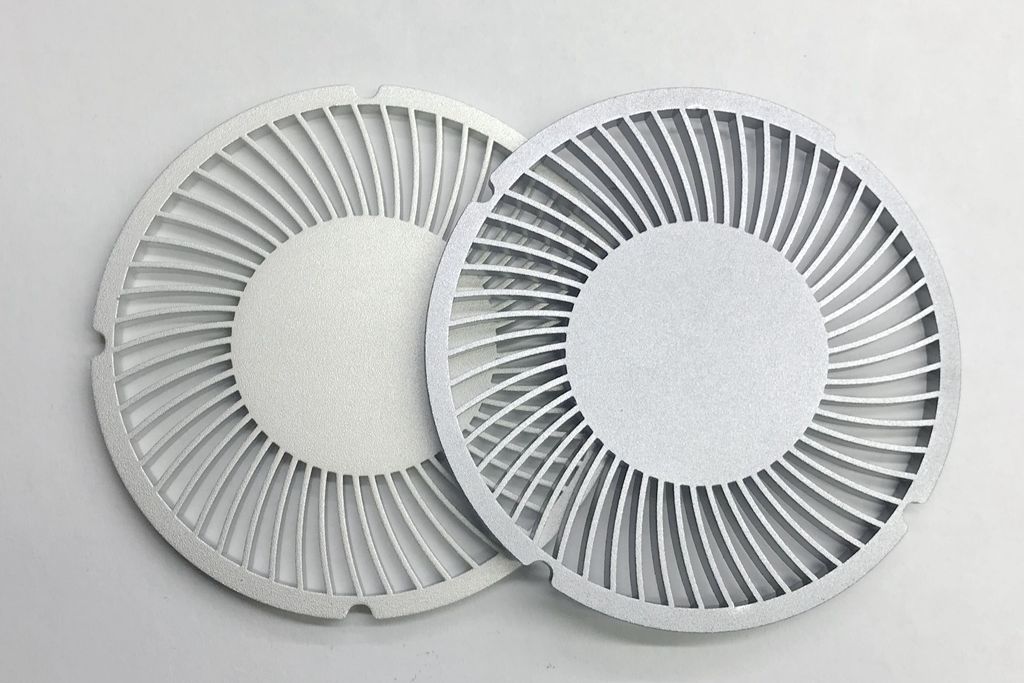
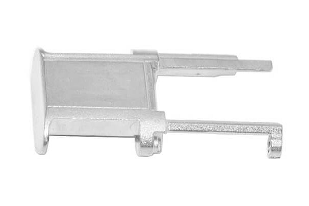
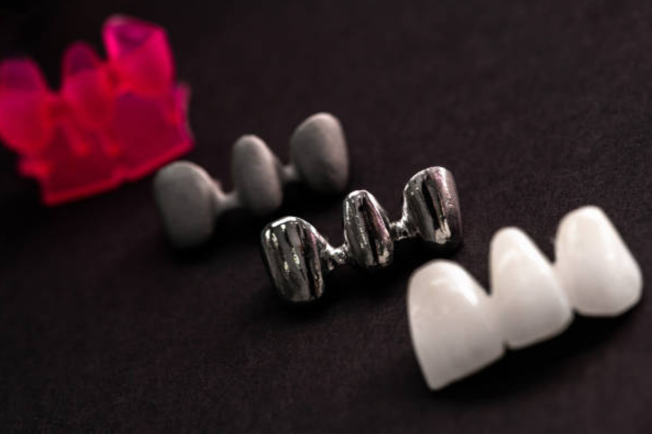
MIM applications expanded because the process can produce compact metal parts with features that may be expensive to machine. Common review examples include hinges, small brackets, latches, gears, connectors, contact parts, RF hardware, and implant-shaped components when buyer specifications and qualification requirements are defined.
Why MIM History Matters for RFQ Decisions
MIM history matters because the process still depends on the same linked controls: powder, binder, molding, debinding, sintering, secondary operations, and inspection. If one stage is ignored during RFQ review, the quoted part may miss a dimensional, material, or assembly requirement.
Buyers should not treat MIM as only an injection molding variant or only a powder metallurgy variant. A good MIM RFQ explains the material grade, part function, critical dimensions, quantity, surface finish, heat treatment, secondary machining, and acceptance criteria.
RFQ Information for Modern MIM Parts
Useful RFQ inputs include a STEP file, 2D drawing, material grade or property target, annual volume, tolerance priority, threads or press-fit areas, surface finish, heat treatment, and inspection records such as dimensional report, CMM report, hardness test, material certificate, or functional test when required.
Related FAQs
Which materials are suitable for Metal Injection Molding MIM?
Why are custom Metal Injection Molding services suitable for high-volume production?
What tooling considerations are important for high-volume MIM production?
How can custom MIM services maintain part consistency across large production runs?
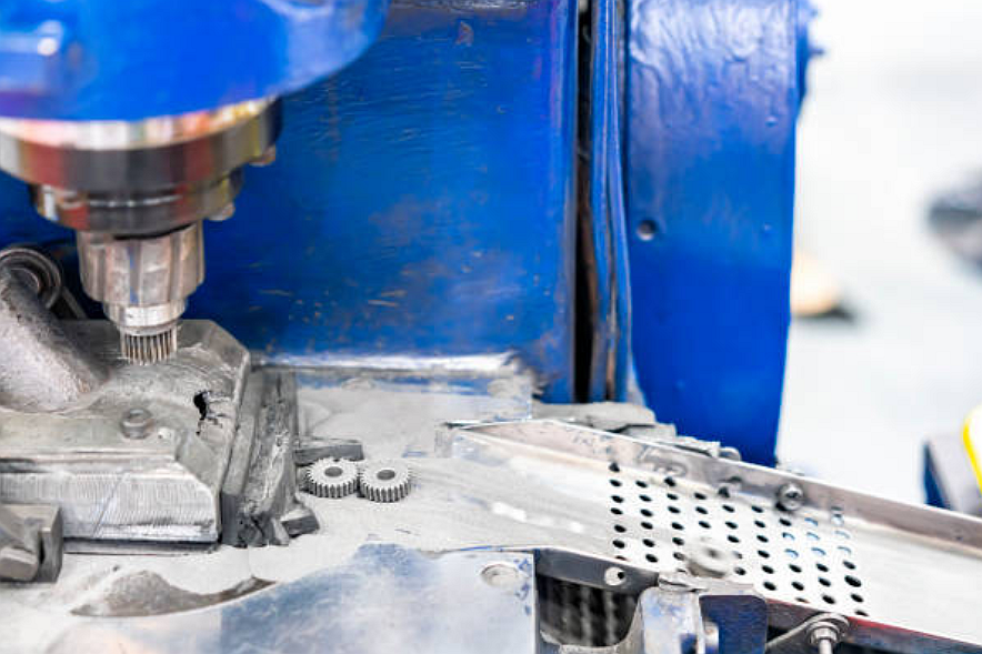
Can secondary machining improve tolerances for metal injection molded components?
What quality inspection methods are used for tight-tolerance MIM components?