How Gas-Assisted Injection Molding Creates Lightweight, Rigid Plastic Parts
This article explains how gas-assisted injection molding creates lightweight, rigid plastic parts by using inert gas pressure to form hollow channels and pack thick sections during the molding cycle. Buyers evaluating gas-assisted molding should define part size, wall thickness, rib layout, cosmetic surfaces, material, gas channel location, gate position, inspection needs, and whether the RFQ problem is weight reduction, sink mark control, stiffness, or conversion from conventional injection molding.
Gas-Assisted Injection Molding RFQ Decision
Gas-assisted injection molding is a specialized plastic injection molding route that injects nitrogen or another inert gas into the molten core of a molded part. The gas pushes plastic against the mold wall, helps pack thick sections, and can create hollow internal channels where the part design allows.
The buyer decision is whether gas-assisted molding solves a real manufacturing problem. It may be useful for large handles, thick ribs, structural covers, long flow paths, or plastic parts that need stiffness with lower weight. It may not be appropriate for every thin-wall part, small precision component, or design with no suitable gas path.
RFQ review should focus on part geometry and acceptance criteria. The gas channel must be controlled so the part remains strong, stable, and visually acceptable. Buyers should define cosmetic surfaces, load points, assembly datums, allowable sink marks, weld line concerns, and any leak, pressure, or fit checks needed for approval.
How Gas Pressure Forms Hollow Channels and Packs Thick Sections
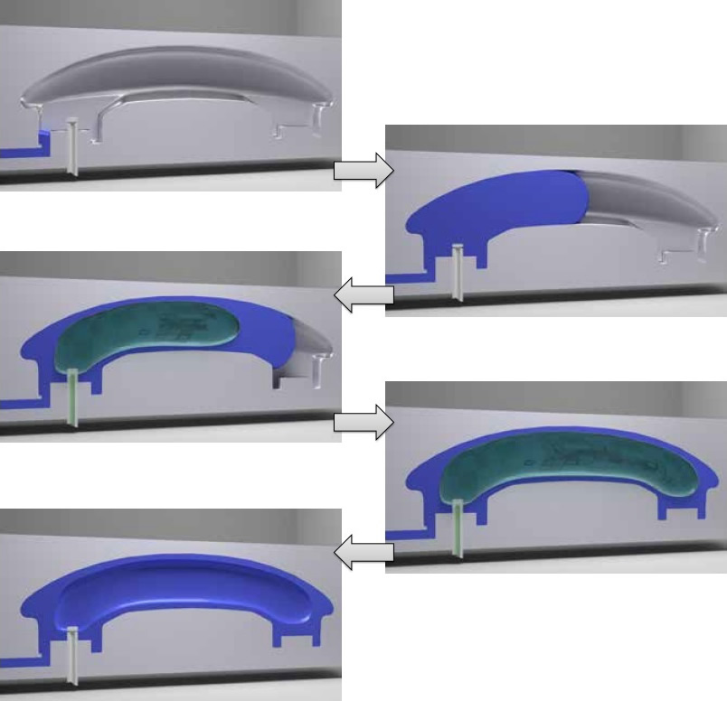
The process begins with a short shot or controlled polymer fill, followed by gas injection into selected molten areas. The gas advances through the lower-resistance molten core, displacing plastic and packing it against the cavity surface. During cooling, gas pressure can help reduce sink marks and support thick sections until the plastic solidifies.
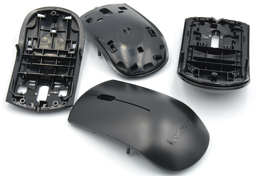
Gas-assisted molding requires more process control than standard injection molding. Shot size, melt temperature, gas delay time, gas pressure, gas volume, cooling time, gate design, and gas pin location can all affect the final hollow channel. If the gas path is not controlled, defects may include gas fingering, blow-through, short shot, sink, burn marks, weak sections, or cosmetic flow marks.
Design Features Suited to Gas-Assisted Injection Molding
Gas-assisted molding is usually considered when a plastic part has thick handles, large ribs, box sections, long flow lengths, structural rails, or cosmetic surfaces over thick internal features. The process can help reduce molded weight while maintaining stiffness when the gas channel supports the load path instead of weakening it.
Designers should plan gas channels intentionally. A gas channel should connect to the correct thick section, avoid breaking through cosmetic surfaces, and avoid disrupting bosses, snap fits, sealing surfaces, or assembly datums. Gas-assisted molding is not a repair method for any thick-wall design; it works best when the part is designed around controlled gas flow.
Material choice also matters. ABS, PC/ABS, PC, PP, nylon, and other thermoplastics behave differently in melt flow, shrinkage, stiffness, surface finish, and gas penetration. Buyers should define the resin grade, filler content, color, texture, and operating environment before gas-assisted tooling is reviewed.
Mold, Gate, Gas Channel, and Material Requirements
Gas-assisted injection molds need a coordinated design for melt flow and gas flow. The mold may require gas pins, gas channels, overflow wells, special venting, pressure control, and a process window that keeps the core molten long enough for gas penetration. Gate location and gas entry should be reviewed together because the gas will follow the easiest path through the molten polymer.
The tooling quote should identify whether the part needs a dedicated gas-assisted mold or whether the design can be adjusted for conventional molding. Gas-assisted molds may add cost through gas hardware, process development, mold trials, and inspection, but those costs may be justified if the route reduces weight, sink marks, or assembly issues.
Gas-Assisted vs Conventional Injection Molding vs Structural Foam
Conventional injection molding remains the better baseline for many smaller, thinner, or simpler parts. Structural foam molding can reduce weight through a foamed core, but it produces a different internal structure and surface behavior. Gas-assisted molding is different because it uses pressurized gas to form defined hollow channels and pack selected thick areas.
Process Route | Best Fit | Main Risk | Buyer Decision Point |
|---|---|---|---|
Conventional injection molding | Thin to moderate wall plastic parts with stable fill and packing | Sink, warp, high packing pressure in thick areas | Can wall thickness and ribs be designed for normal molding? |
Gas-assisted injection molding | Large or thick plastic parts needing hollow channels, stiffness, or sink control | Gas blow-through, uncontrolled channel path, weak sections | Can the part be designed around a controlled gas path? |
Structural foam molding | Lower-density parts where foamed core behavior is acceptable | Surface finish limits, variable cell structure, lower detail control | Is a foamed internal structure acceptable for the application? |
Defects and Inspection Evidence for Gas-Assisted Plastic Parts
Gas-assisted injection molded parts should be checked for both ordinary injection molding defects and gas-specific defects. Ordinary defects may include sink marks, weld lines, flash, short shots, warpage, burn marks, and ejector marks. Gas-specific defects may include gas fingering, gas blow-through, unstable hollow sections, trapped gas marks, or inconsistent wall thickness around the channel.
Inspection evidence should match the part function. Useful checks may include dimensional reports, visual inspection standards, section cuts during development, weight checks, CMM inspection, assembly fit checks, surface review, and functional testing based on buyer requirements. For parts with internal channels, early sampling should confirm whether the gas channel is where the design expects it to be.
Quality control should also include process monitoring. Shot size, gas pressure, gas timing, melt temperature, mold temperature, and cooling time should stay within the qualified process window. If the buyer changes resin grade, colorant, filler, or wall thickness after tooling release, the gas-assisted process may need revalidation.
When Gas-Assisted Injection Molding May Not Fit
Gas-assisted molding may not fit very small parts, simple thin-wall parts, parts without a suitable gas channel, parts with many isolated cosmetic surfaces, or parts where hollow sections could reduce strength at load points. It may also be unnecessary when conventional rib design, coring, wall-thickness adjustment, or material selection can solve sink and stiffness problems.
Buyers should compare gas-assisted molding with conventional injection molding, structural foam, two-shot molding, overmolding, CNC prototyping, and part redesign. The best route is the one that answers the actual RFQ problem with manageable tooling risk and clear inspection criteria.
RFQ Information Needed for Gas-Assisted Injection Molding
A complete RFQ should include the 3D model, 2D drawing, resin grade, color, filler content, part size, wall thickness, rib layout, target weight, critical dimensions, cosmetic surfaces, load points, assembly interfaces, surface finish, gate restrictions, gas channel expectations, and inspection requirements.
If the buyer is considering conversion from conventional molding, the RFQ should identify the current defects or cost problem, such as sink marks, high part weight, warpage, long cycle, or high packing pressure. That information helps the tooling team judge whether gas-assisted molding is the right route or whether a simpler design change may be enough.
Related FAQs