What is Ceramic Injection Molding | Advantages and Applications
Ceramic injection molding (CIM) is an injection molding and sintering process for small, complex ceramic parts such as alumina insulators, zirconia housings, ceramic pins, wear inserts, sensor components, and electronic device parts. This article explains how CIM works, where its advantages apply, and what buyers should confirm before an RFQ because material grade, feedstock flow, sintering shrinkage, tooling, secondary finishing, and inspection requirements all affect whether CIM is the right manufacturing route.
How Ceramic Injection Molding Converts Feedstock Into Sintered Ceramic Parts
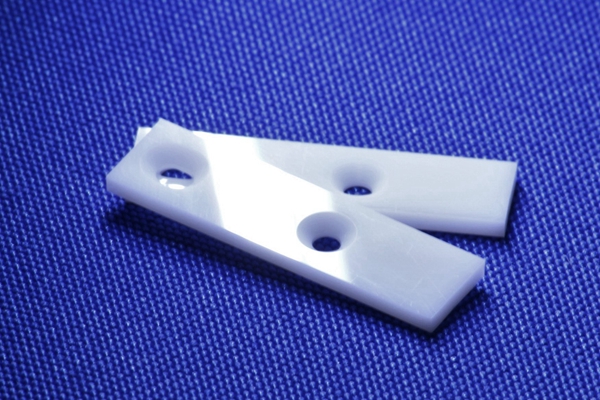
Ceramic injection molding uses a ceramic powder and binder feedstock that can flow into an injection mold. After molding, the binder is removed and the ceramic compact is sintered at high temperature to create the final ceramic part. The final component is not a plastic-filled ceramic part; the binder is a temporary carrier that allows the ceramic powder to be molded.
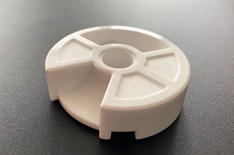
The CIM process is useful because injection molding can form undercuts, thin ribs, small holes, curved surfaces, and repeated miniature features that may be expensive to machine from sintered ceramic blocks. The process still has limits. Debinding, sintering shrinkage, brittle features, tool venting, gate location, and furnace support must be reviewed before production tooling.
CIM Process Stage | What Happens | Manufacturing Risk to Control | Buyer Confirmation Needed |
|---|---|---|---|
Feedstock preparation | Ceramic powder is compounded with binder and additives. | Powder grade, particle size, binder system, and feedstock flow affect mold filling and sintering. | Material family, color requirement, dielectric or wear requirement, and part function. |
Injection molding | Feedstock is injected into a precision mold cavity. | Gate marks, weld lines, trapped air, and fragile green features can affect yield. | Cosmetic surfaces, functional surfaces, and allowable gate or parting line locations. |
Debinding | The binder is removed from the molded green part. | Rapid binder removal can cause cracking, voids, or deformation. | Wall thickness, internal cavities, and any features that may trap binder. |
Sintering | The debound part densifies and shrinks into the final ceramic component. | Shrinkage, warpage, density variation, and support contact marks must be controlled. | Critical dimensions, flatness, datum surfaces, and inspection method. |
Finishing and inspection | Parts may be ground, polished, lapped, metallized, coated, or assembled. | Hard ceramic finishing adds cost and may be needed for tight surfaces. | Surface roughness, dimensional report, visual standard, and functional test needs. |
What Buyer Problems CIM Solves for Small Complex Ceramic Parts
CIM is often chosen when the buyer needs ceramic properties and molded geometry at production volume. The process can reduce repeated ceramic machining when the part has small features, curved geometry, side holes, thin sections, or multiple functional surfaces that would be slow to grind one by one.
The main advantage is design freedom for ceramic materials. Buyers can consider CIM when the application needs electrical insulation, wear resistance, chemical stability, thermal stability, low thermal expansion, or a hard cosmetic surface. CIM is also useful when the same small ceramic part must be produced repeatedly after tooling has been qualified.
The advantage is not automatic for every ceramic component. If annual volume is low, if the part is large and simple, if the geometry can be pressed easily, or if only a few prototypes are required, powder pressing, ceramic machining, additive manufacturing, or another route may be more practical.
Which Ceramic Materials Fit CIM: Alumina, Zirconia, Silicon Carbide, and Silicon Nitride
Material choice should come before tooling design. The CIM material affects feedstock flow, sintering temperature, shrinkage behavior, final color, mechanical performance, insulation behavior, and finishing cost.
Ceramic Material | Typical CIM Part Reason | Buyer Decision Before RFQ |
|---|---|---|
Electrical insulators, wear parts, guides, nozzles, and structural ceramic components. | Confirm alumina grade, dielectric requirement, wear surface, color, and surface finish. | |
Hard cosmetic parts, precision wear components, small housings, and high-strength ceramic details. | Confirm color, toughness requirement, aging risk in the operating environment, and polishing standard. | |
Wear, thermal, and chemical environments where silicon carbide properties are needed. | Confirm grade availability, sintering route, surface finish, and whether the design is suitable for CIM. | |
Wear-resistant and thermal-stress components when silicon nitride performance is specified. | Confirm material availability, load condition, finishing allowance, and acceptance tests. |
CIM Design Risks: Shrinkage, Debinding, Sintering Distortion, and Brittle Features
CIM design review should start with shrinkage and geometry. Ceramic feedstock shrinks during debinding and sintering, so the mold cavity is intentionally larger than the final part. Critical dimensions, datum surfaces, hole positions, flatness, and wall sections must be marked clearly before tooling review.
Brittle features need special attention. Sharp internal corners, very thin posts, long unsupported arms, abrupt wall changes, and deep blind pockets can increase cracking, deformation, or handling damage during the green and brown part stages. Radii, uniform wall transitions, support surfaces, and realistic inspection datums help reduce manufacturing risk.
Undercuts are possible in injection molding, but the mold must be able to release the green ceramic part without damage. Side actions, lifters, core pins, and parting line choices should be reviewed against the ceramic feedstock strength before the buyer freezes the design.
When CIM Is Better Than Powder Pressing, Machining, or 3D Printing
CIM is usually a stronger route when the part is small, complex, repeated in production volume, and made from a ceramic material that can be compounded into stable feedstock. Powder pressing molding may be better for simpler axial shapes, while ceramic machining may be better for very low volume or features that need post-sintered precision.
Manufacturing Route | Suitable Ceramic Part Scenario | When to Avoid This Route |
|---|---|---|
Ceramic injection molding | Small complex ceramic parts with repeated production demand and moldable geometry. | Avoid when tooling cost cannot be justified or when the geometry creates high debinding risk. |
Powder pressing molding | Simple discs, rings, sleeves, and axial ceramic shapes that press well. | Avoid when side features, undercuts, and complex 3D surfaces dominate the design. |
Ceramic machining | Prototype parts, tight datum surfaces, holes, slots, and finishing after sintering. | Avoid as the main route when repeated complex geometry would create high machining time. |
Ceramic 3D printing | Early prototypes, special channels, and geometry validation before production tooling. | Avoid for production unless material properties, surface finish, and economics are approved. |
Where CIM Parts Are Used in Industrial Assemblies and Electronics
CIM parts are used where ceramic properties and compact geometry matter together. Typical applications include electrical insulators, sensor housings, pump and valve components, ceramic guides, wear pads, cutting or forming inserts, connector bodies, ferrules, cosmetic ceramic covers, and small parts for electronic assemblies.
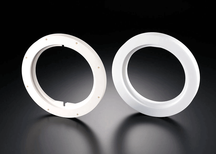
For electronics and communication devices, CIM may support ceramic housings, insulating parts, antenna-related components, and cosmetic covers when the required material, color, strength, and surface quality are defined. For industrial equipment, CIM may support components that need wear resistance, insulation, chemical stability, or thermal resistance in a compact shape.
Regulated, safety-related, or customer-qualified applications should be handled with cautious qualification language. The buyer should define the required standard, test plan, documentation, and acceptance criteria before tooling. Final validation remains the buyer's responsibility.
Cost and Inspection Inputs Buyers Should Define Before a CIM RFQ
CIM cost is driven by tooling, feedstock, part size, annual quantity, cycle time, debinding and sintering yield, finishing operations, and inspection documentation. Buyers should separate must-have functional requirements from cosmetic preferences because hard ceramic finishing can become a major cost driver.
Buyer Requirement | CIM Manufacturing Impact | Useful RFQ Detail |
|---|---|---|
Material grade | Powder availability, sintering behavior, color, and property target depend on ceramic material. | Specify alumina, zirconia, silicon carbide, silicon nitride, or approved equivalent. |
Critical dimensions | Mold shrinkage compensation and inspection planning depend on functional dimensions. | Mark datums, hole positions, flatness, fits, and surfaces that need post-sintering finishing. |
Surface finish | Polishing, lapping, grinding, coating, or metallization can change unit cost. | Define roughness, cosmetic standard, visible surfaces, and sample approval needs. |
Inspection documentation | Reports and tests affect production control and quotation time. | Request CMM report, dimensional report, material certificate, density check, visual standard, or functional test only where needed. |
Production stage | Prototype, pilot lot, and mass production may require different tooling and validation decisions. | State sample quantity, pilot quantity, annual volume, and approval process. |
CIM is strongest when the buyer has a stable small ceramic part design, realistic production volume, clear material requirements, and defined inspection criteria. When those inputs are available, ceramic injection molding can turn difficult ceramic geometry into a repeatable molded and sintered production route.
Related FAQs