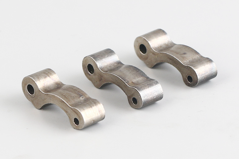
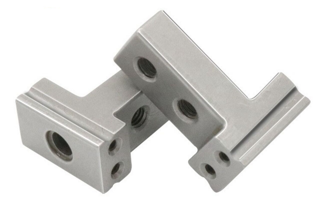
What tolerances can precision metal injection molding services typically achieve?
Precision metal injection molding services can achieve useful tolerances for many small complex metal parts, but the achievable tolerance depends on part size, geometry, material, shrinkage control, tooling, sintering support, secondary operations, and inspection method. This FAQ explains how Neway evaluates MIM tolerance for gears, cams, brackets, thin-wall parts, lock components, medical hardware, connector parts, and precision metal mechanisms. The practical RFQ problem is to decide which dimensions can be controlled as-sintered and which dimensions need machining, sizing, grinding, or special inspection after MIM.
What does typical MIM tolerance mean?
Typical MIM tolerance means the dimensional variation that can be expected when the part is designed for metal injection molding and the process is controlled through molding, debinding, sintering, and finishing. MIM is a near-net-shape process, but it is not a no-variation process. The part shrinks during sintering, and this shrinkage must be predicted and controlled.
Neway does not judge tolerance from a generic table alone. The review considers the material, part size, wall thickness, feature type, datum scheme, tool design, sintering orientation, heat treatment, secondary machining, and inspection plan. A simple external length, a small bore, a gear tooth, and a thin wall may not have the same tolerance capability.
MIM tolerance item | What controls it | Typical risk | RFQ detail to define |
|---|---|---|---|
Overall length or width | Shrinkage compensation, material, wall balance | Scale variation across the part | Critical dimension status and datum reference |
Bore, shaft, or hole position | Tooling, sintering support, secondary machining | Ovality, positional drift, fit problems | Mating part, fit requirement, inspection method |
Gear tooth or cam profile | Mold detail, shrinkage, surface finish, wear requirement | Profile error or motion noise | Profile data, contact load, gear mesh, gauge plan |
Thin wall or flatness | Wall thickness balance, support, sintering orientation | Warping, bowing, edge distortion | Wall map, flatness target, support surfaces |
Which dimensions are easier or harder to hold in MIM?
Dimensions that are well supported, uniform in section, away from severe wall transitions, and measured from stable datums are usually easier to control. External features with clear datum references and moderate tolerance requirements often fit the MIM route well.
Dimensions that involve long thin sections, unsupported ribs, small deep holes, tight positional relationships, high flatness requirements, or contact profiles can be harder to hold as-sintered. These features may still be possible, but they need tooling compensation, support strategy, fixture design, or secondary operations.
Buyers should mark dimensions as critical-to-function, assembly-important, cosmetic, or reference-only. This prevents unnecessary cost on non-critical dimensions while giving proper attention to datums, fits, and moving interfaces.
Which design, material, and process factors affect MIM tolerance?
Design factors include wall thickness balance, rib geometry, hole size, slot length, boss location, corner radius, parting line, gate location, and sintering support. Material factors include powder characteristics, alloy chemistry, binder system, and sintering behavior. Process factors include molding parameters, debinding, furnace profile, atmosphere, heat treatment, machining, and finishing.
Shrinkage is central to tolerance. The mold is made larger than the final part, and the part shrinks during sintering. If shrinkage varies by material, geometry, or orientation, final tolerance can shift. Neway reviews shrinkage behavior and tool compensation before quoting tight dimensions.
Surface treatments can also affect tolerance. Polishing, tumbling, passivation, PVD, nitriding, coating, and heat treatment can change dimensions or surface condition. Buyers should define coating thickness limits, no-coating zones, and functional surfaces during the RFQ stage.
When are secondary operations needed for tighter MIM dimensions?
Secondary operations are needed when the final function requires tighter control than the as-sintered route can provide. Common examples include precision bores, threads, bearing seats, sealing faces, gear datums, latch contact surfaces, and critical mounting surfaces.
Neway may recommend CNC machining, reaming, tapping, grinding, sizing, coining, polishing, or fixture-based finishing depending on the part. The buyer should identify which dimensions justify secondary operations because each added operation affects cost, lead time, inspection, and production capacity.
Feature needing tighter control | Possible secondary operation | Reason for operation | Buyer input |
|---|---|---|---|
Bore or bearing seat | Reaming, CNC machining, grinding | Improves fit with shaft or pin. | Fit class, mating part, measurement method |
Threaded hole | Tapping or thread forming after sintering | Controls thread strength and assembly quality. | Thread specification, torque, insert option |
Sealing or datum face | Machining, grinding, lapping, polishing | Controls flatness, roughness, or datum alignment. | Flatness, roughness, sealing requirement |
Gear or cam interface | Profile inspection, polishing, local finishing | Controls motion, backlash, wear, and noise. | Gear data, cam profile, cycle requirement |
How are MIM tolerances inspected and controlled?
Neway controls MIM tolerance by connecting tooling, shrinkage, process settings, sintering, secondary operations, and inspection. Inspection may include first article reports, CMM measurement, optical inspection, gauges, surface roughness checks, hardness checks, coating checks, and functional tests.
For high-volume MIM, statistical process control can be used for selected critical dimensions. The selected dimensions should be tied to final function, such as gear mesh, latch movement, shaft fit, sealing, or assembly alignment. Monitoring non-critical dimensions without a functional reason adds cost without improving the part.
Inspection should use the same datum logic as the drawing. If the drawing datum scheme does not match the assembly function, the reported tolerance may not predict real fit. Buyers should provide mating component drawings and assembly requirements when tolerance is important.
What RFQ details help Neway review MIM tolerance?
A useful RFQ should include 3D models, 2D drawings, datum scheme, critical dimensions, material grade, wall thickness, part function, mating parts, tolerance requirements, surface finish, heat treatment, coating, secondary operation expectations, inspection method, and annual volume.
Neway can then identify which dimensions are practical as-sintered, which dimensions need secondary operations, and which design features should be adjusted before tooling. Tolerance planning is strongest when the buyer separates functional dimensions from general drawing dimensions early in the RFQ.
Related FAQs
Which design factors affect dimensional accuracy in precision MIM parts?
How are tight-tolerance components controlled during the MIM shrinkage process?
What quality inspection methods are used for tight-tolerance MIM components?
Can secondary machining improve tolerances for metal injection molded components?
What tooling considerations are important for high-volume MIM production?
How can custom MIM services maintain part consistency across large production runs?