What Kind of Geometric Shapes and Complex Details Can Metal Injected Parts Achieve?
MIM Geometric Complexity RFQ Decision: Metal injection molding can produce small complex metal parts with ribs, bosses, slots, holes, curved surfaces, textured details, fine teeth, and integrated features when the geometry supports injection molding, debinding, sintering, and inspection. This article explains what shapes MIM parts can achieve, how material grade and sintering shrinkage affect detail control, and what buyers should define before requesting a quotation for gears, hinges, lock parts, brackets, levers, connectors, housings, and miniature structural components. The practical RFQ problem is deciding which features can be molded directly and which features need secondary machining, sizing, heat treatment, or inspection planning.
MIM is strongest when the buyer needs many small metal parts with complex geometry that would be slow to machine from bar stock or difficult to assemble from multiple pieces. The process uses metal powder feedstock, injection molding, debinding, and sintering to form dense metal components. Buyers should still treat every complex feature as a manufacturability question because flow, tooling, shrinkage, distortion, and inspection access all affect the final result.
What MIM Geometric Shapes Are Practical for Small Metal Parts?
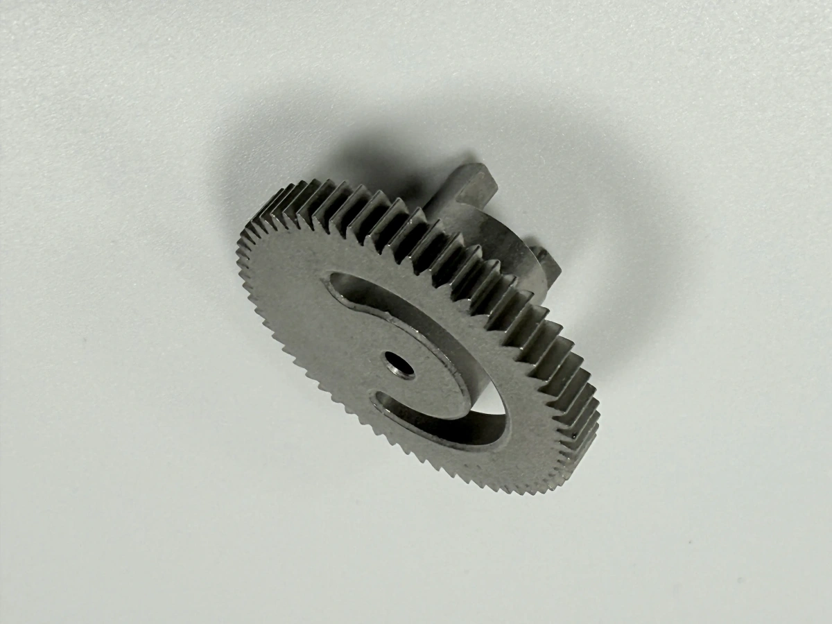
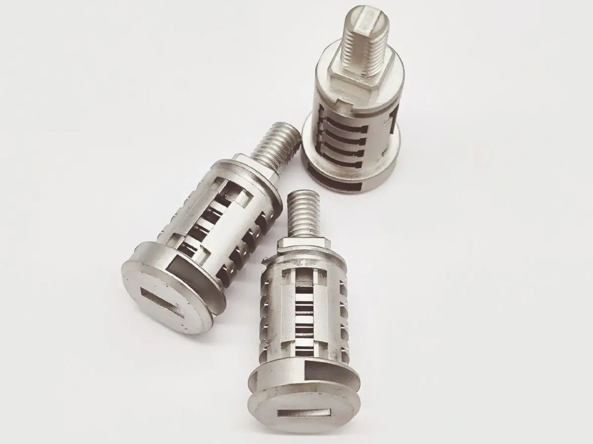
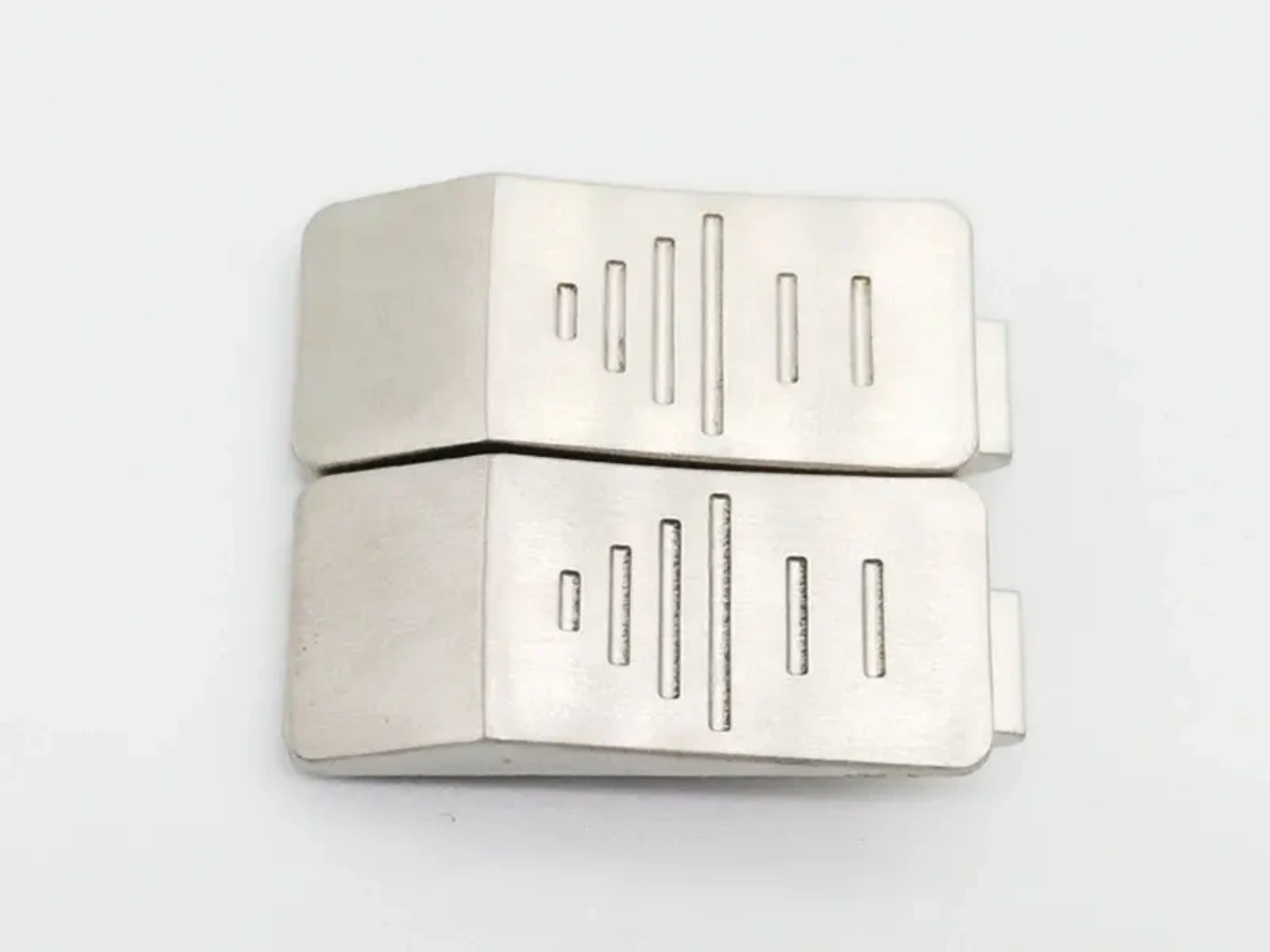
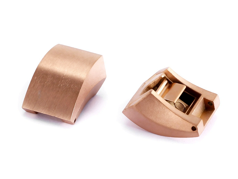
MIM can support compact three-dimensional shapes with multiple functional features in one molded metal component. Practical examples include curved housings, gear-like forms, latches, trigger parts, lock components, hinge elements, small brackets, levers, clips, connector shells, and miniature mechanical parts with combined cosmetic and functional surfaces.
The engineering reason is that MIM starts with a moldable feedstock, so the green part can carry details that resemble plastic injection molded geometry before debinding and sintering convert the feedstock into a metal part. MIM can reduce assembly steps when bosses, ribs, grooves, mounting pads, and alignment features are molded into the same part instead of being machined or joined later.
The RFQ implication is direct: buyers should provide a complete 3D model and identify which surfaces are functional, cosmetic, load-bearing, or reference datums. A complex outside shape may be easy to mold, while a hidden internal corner, deep blind hole, thin unsupported section, or inaccessible inspection surface may require design review.
How Do Thin Walls, Ribs, Bosses, and Slots Affect MIM Feasibility?
Thin walls, ribs, bosses, and slots are possible in MIM, but the geometry must allow stable molding, controlled debinding, even sintering shrinkage, and reliable handling. These features should be reviewed together because isolated feature checks can miss warpage, cracking, filling, and tool-release risks.
Wall thickness balance is important. A part with a very heavy boss next to a thin wall can shrink unevenly. Long unsupported ribs can bend or distort during processing. Narrow slots can be difficult to fill, debind, clean, or inspect. Bosses for screws, pins, or inserts must be reviewed for strength, shrinkage, and any secondary operation.
Buyers should mark critical ribs, mounting bosses, contact pads, slots, and sealing or bearing surfaces on the drawing. If a feature controls assembly, torque, wear, or alignment, the RFQ should state the function and inspection method instead of listing only the CAD geometry.
Can MIM Produce Holes, Undercuts, Teeth, Threads, and Internal Details?
MIM can produce many holes, grooves, teeth, recesses, and external details directly from tooling, but not every internal feature should be molded as-is. Tooling access, ejector layout, parting line location, debinding path, sintering support, and inspection access decide whether the feature is practical.
Through holes and open grooves are often easier to evaluate than deep blind holes or closed internal passages. Fine teeth may be practical when the tooth form supports powder feedstock flow and sintering control. Threads can sometimes be molded or formed later, but critical threads often need secondary tapping, thread rolling, inserts, or machining depending on load and tolerance.
The RFQ should separate molded features from post-processed features. Buyers should identify holes that need reaming, threads that need tapping, surfaces that need grinding or machining, and edges that need deburring or finishing. This distinction helps prevent the quotation from assuming molded detail where post-processing is actually required.
How Do Debinding, Sintering Shrinkage, and Material Grade Limit Geometry?
Debinding and sintering are the main reasons MIM geometry needs early engineering review. During debinding, binder leaves the molded part. During sintering, the metal powder densifies and the part shrinks. Material grade, powder size, binder system, furnace profile, part mass, and support method all influence the final geometry.
Metal sintering can turn a molded green part into a dense metal component, but sintering does not shrink every feature in isolation. Thick-to-thin transitions, asymmetric features, large flat sections, delicate projections, and long unsupported spans can move differently. Stainless steels, low-alloy steels, tool steels, magnetic alloys, tungsten alloys, titanium alloys, and cobalt alloys should be reviewed against the required strength, corrosion resistance, wear behavior, and dimensional control.
The RFQ implication is that buyers should define material grade and acceptance criteria together. A geometry that is reasonable in one MIM material may need adjustment in another material. For critical features, the buyer should request DFM review, shrinkage review, sample inspection, and any required secondary operations before approval.
Which Geometry Details Should Buyers Define in the RFQ?
Buyers should define the feature function, not only the feature shape. A molded groove for appearance has a different risk level than a groove that holds a spring, seal, shaft, magnet, latch, or connector. A cosmetic curve has different requirements than a bearing surface or gear tooth contact face.
MIM Geometry Feature | Manufacturing Risk | RFQ Detail Needed | Review or Inspection Evidence |
|---|---|---|---|
Thin wall, rib, or web | Incomplete filling, bending, cracking, sintering distortion, or handling damage. | Wall function, load direction, adjacent thick sections, cosmetic side, and allowable distortion. | DFM review, sample dimensional report, fixture check, and visual inspection if required. |
Boss, post, or mounting pad | Uneven shrinkage, sink-like geometry risk, weak thread engagement, or secondary machining need. | Fastener type, insert requirement, torque requirement, datum surface, and assembly load. | Section review, thread inspection, pull or torque test if specified, and CMM report. |
Hole, slot, groove, or pocket | Tooling access issue, debinding difficulty, burr risk, shrinkage variation, or inspection access limit. | Through or blind feature, mating part, edge requirement, post-machining allowance, and gauge requirement. | Pin gauge check, CMM report, fixture inspection, or post-machining inspection record. |
Gear tooth, latch surface, or fine mechanical detail | Tool wear, tooth-form variation, sintering distortion, surface finish issue, or wear risk. | Contact surface, motion direction, wear requirement, heat treatment, and critical profile area. | Profile inspection, functional fit test, hardness check if required, and surface finish review. |
When Should MIM Be Compared With CNC Machining, Casting, or Powder Pressing?
MIM should be compared with other processes when the part is large, has simple geometry, needs a very tight local tolerance everywhere, or uses geometry that blocks molding and debinding. MIM, CNC machining, die casting, and investment casting each solve different geometry and volume problems.
CNC machining can be better for low-volume parts, very precise datum surfaces, or simple metal blocks with many machined features. Investment casting can be better for larger complex metal forms. Powder pressing can be useful for simpler powder metal shapes with a more direct press direction. MIM becomes attractive when the buyer needs small complex metal parts with integrated features and a production quantity that can justify tooling.
The RFQ should state whether the buyer is optimizing for geometry integration, surface finish, tight local dimensions, material performance, tooling cost, production volume, or validation speed. This helps the supplier decide whether MIM alone is suitable or whether MIM plus secondary machining is the more realistic route.
What Neway Precision Reviews for Complex MIM Part Geometry
Neway Precision reviews complex MIM part RFQs by checking feedstock flow, gate location, parting line, wall thickness balance, ribs, bosses, holes, slots, threads, undercuts, ejection, debinding path, sintering support, material grade, secondary machining, heat treatment, surface finishing, and inspection criteria. The review connects MIM mold design, MIM materials, sintering behavior, and buyer acceptance requirements.
A complete RFQ should include the 3D CAD model, 2D drawing, material grade or required property, critical dimensions, datum scheme, surface finish, thread and hole requirements, heat treatment, coating or passivation needs, expected quantity, inspection reports, and the purpose of each complex feature. Buyers can also review MIM materials before selecting stainless steel, tool steel, magnetic alloy, tungsten alloy, titanium alloy, or cobalt alloy options.
Related FAQs
Can OEM Metal Injection Molding Services Produce Complex Stainless Steel Parts With Custom Features?
How Are Tight Tolerance Components Controlled During The MIM Shrinkage Process?
Which Design Factors Affect Dimensional Accuracy In Precision MIM Parts?
What Quality Inspection Methods Are Used For Tight Tolerance MIM Components?