Metal Injection Molding Services for Small Complex Metal Parts
Small Complex MIM Part RFQ Decision: This article explains how buyers can specify metal injection molding for small complex metal parts that need thin walls, miniature features, internal slots, fine teeth, curved surfaces, or repeated high-volume production. The part types include miniature gears, lock parts, electronic hardware, medical device components, small brackets, connector parts, wear features, and stainless steel mechanism parts. The practical RFQ problem is deciding which MIM material, feedstock route, debinding and sintering controls, shrinkage allowance, secondary machining, surface treatment, and inspection evidence should be quoted before the buyer validates fit, strength, wear, corrosion resistance, and production repeatability.
MIM is useful when a small metal part is too complex for efficient machining but still needs metal properties after sintering. Buyers should not treat MIM as only a shape process. The RFQ should define the functional surfaces, critical dimensions, material grade, expected production stage, and inspection scope so the supplier can quote tooling, sintering control, and any secondary operations realistically.
When Is MIM The Right Route For Small Complex Metal Parts?
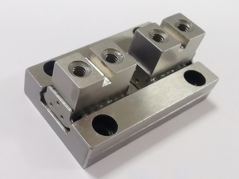
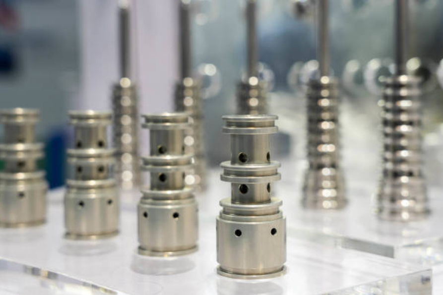
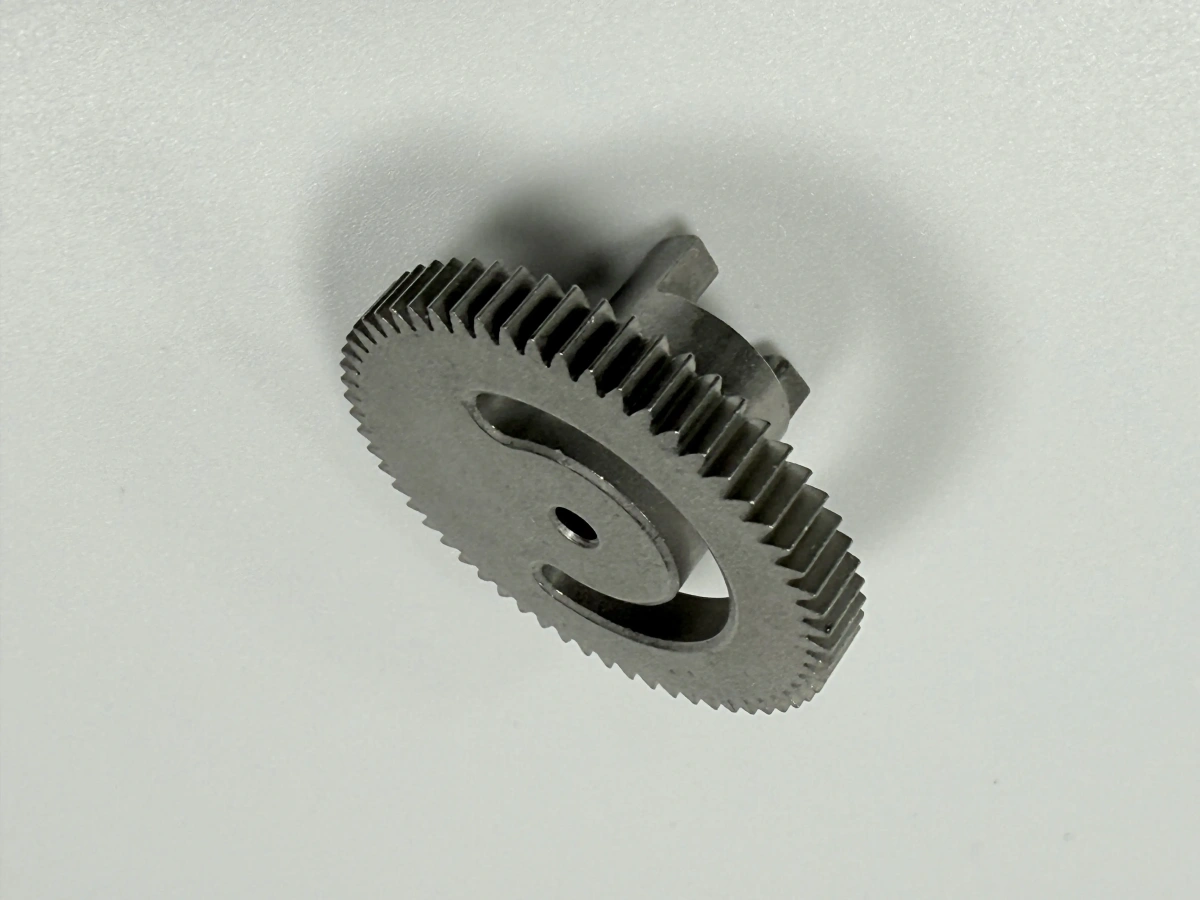
MIM should be reviewed when the part combines small size, complex geometry, and repeated production demand. Typical MIM candidates include thin-wall components, miniature gears, latch parts, surgical tool features, connector hardware, lock mechanism parts, actuator elements, and small stainless steel brackets. MIM is less attractive when the part is simple enough for stamping or machining, when volume cannot support tooling, or when all critical surfaces require heavy machining after sintering.
The buyer decision should be direct. Choose MIM for a small complex metal part when the design benefits from near-net shaping, integrated features, and repeatable production. Keep CNC machining in the comparison when the part is a prototype, a low-volume design, or a component dominated by tight machined datums. Background comparisons include how metal injection molding works and MIM versus CNC machining, die casting, and investment casting.
MIM Part Feature | RFQ Question To Answer | Manufacturing Implication | Evidence To Request |
|---|---|---|---|
Thin wall or miniature rib | Where is the minimum wall and is the feature structural? | Mold filling, sintering distortion, and tool design need review | Design review and dimensional inspection plan |
Internal slot or undercut | Can the feature be molded and released without tool conflict? | Mold parting, side action, or redesign may be required | Mold design feedback and feature risk review |
Gear tooth or wear feature | Which surfaces carry load or sliding contact? | Material, heat treatment, and finishing affect performance | Material record, hardness record, and critical dimension report |
Machined datum or threaded hole | Which features must be finished after sintering? | Secondary machining must be included in the quote | CMM report and machining inspection |
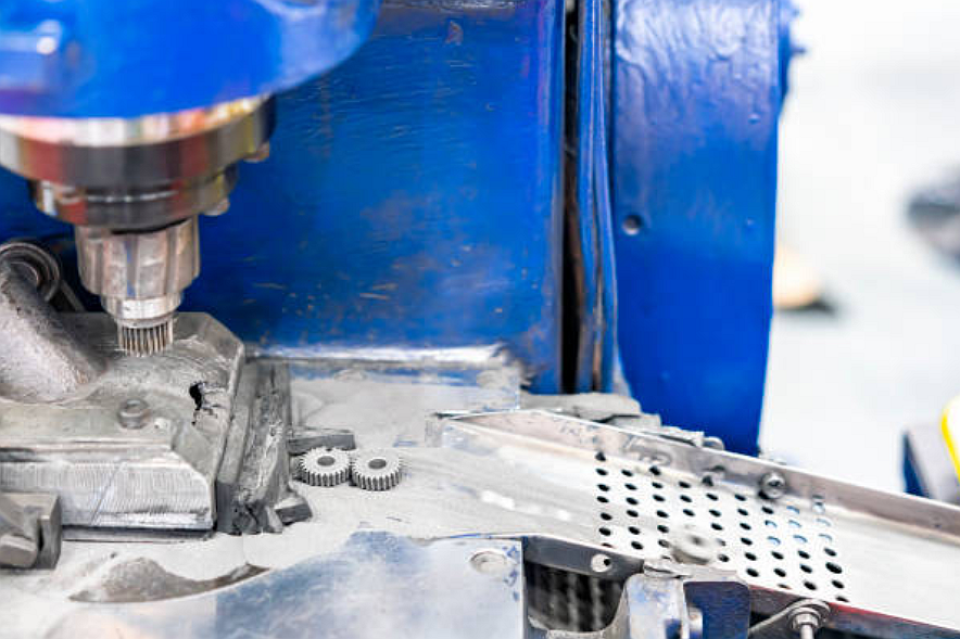
How Do Feedstock, Debinding, And Sintering Affect The RFQ?
The MIM process starts with metal powder and binder compounded into feedstock. The feedstock is injection molded into a green part, debound to remove binder, and sintered to densify the metal. Each stage affects small complex parts because powder size, binder removal, shrinkage, and sintering support can influence final geometry and material behavior.
Buyers should include the part function and critical dimensions before asking for process pricing. A thin-wall electronics part, a stainless steel surgical feature, and a miniature gear may need different sintering support, material grade, and inspection evidence. Useful process references include MIM metal powder manufacturing methods, metal sintering in MIM and powder metallurgy, and pressureless sintering in MIM.
Which MIM Materials Should Buyers Compare?
MIM material choice should be connected to strength, corrosion exposure, magnetic behavior, wear, hardness, and post-processing requirements. Stainless steels are often reviewed for corrosion resistance and small precision components. Low alloy steels can be reviewed for strength and heat treatment response. Tool steels can be reviewed for wear features. Tungsten alloys, titanium alloys, and specialty alloys may be reviewed when density, heat, or application-specific requirements justify the material.
The RFQ should name candidate grades instead of asking for a generic metal. Buyers can compare MIM 17-4 PH stainless steel, MIM 316L stainless steel, MIM 420 stainless steel, MIM 440C stainless steel, and MIM 4140 alloy steel when reviewing small complex metal parts.
How Should Shrinkage And Tolerances Be Specified?
MIM shrinkage is expected during sintering, so the RFQ should identify which dimensions are critical after sintering. Buyers should mark datums, holes, sliding surfaces, gear features, threads, press-fit areas, and sealing faces. Not every dimension should carry the same tolerance because over-controlling non-functional features can distort the cost and tooling discussion.
Secondary machining should be specified where MIM cannot reasonably control the feature alone. Reaming, tapping, grinding, polishing, or CNC machining may be needed for holes, threads, bearing surfaces, and tight datums. Buyers can use MIM precision and quality consistency and precision MIM services for tight-tolerance components to frame tolerance questions.
What Design Rules Matter For Small Complex MIM Parts?
Design rules should be reviewed before tooling. Wall thickness, rib transitions, sharp corners, holes, undercuts, bosses, parting lines, gate locations, and sintering support all affect the final part. Small complex parts are often sensitive to uneven sections because the material must flow during molding and shrink during sintering.
The RFQ should include 3D CAD, 2D drawings, expected functional surfaces, annual production stage, and any assembly constraints. Buyers should identify whether a feature is required for function or only for appearance. MIM mold design considerations and complex geometries in metal injected parts can support design-for-manufacturing review.
Buyer Requirement | MIM Entity To Define | RFQ Impact |
|---|---|---|
Corrosion-resistant miniature part | 17-4 PH, 316L, passivation, surface finish | Material grade and finishing route |
Wear-resistant small mechanism feature | 420, 440C, heat treatment, contact face | Hardness evidence and post-processing scope |
Tight assembly fit | Datum scheme, hole position, secondary machining | Inspection method and machining allowance |
High-volume production stage | Tooling, sintering control, sampling plan, repeatability evidence | Tooling quote and production release plan |
Which Post-Processing And Inspection Evidence Should Be Quoted?
Post-processing should match the part function. Heat treatment can support hardness or strength. Passivation can support corrosion resistance for stainless steel parts. Polishing, tumbling, blasting, coating, or machining can support surface finish, burr control, or assembly fit. The RFQ should define which operations are required by function and which operations are cosmetic.
Inspection evidence should focus on critical dimensions and material behavior. CMM inspection can support datums, holes, gear features, and mating surfaces. Hardness testing can support heat-treated parts. Material records can support grade selection. Surface finish inspection can support sliding surfaces or sealing features. Buyers can reference passivation for custom metal components, as-machined surface finishes, and CMM dimensional inspection when defining evidence.
What Should Buyers Include In A Small Complex MIM RFQ?
A complete MIM RFQ should include CAD files, 2D drawings, part function, target material grade, annual production stage, critical dimensions, datum scheme, thin-wall features, internal slots, undercuts, holes, threads, surface treatment, heat treatment, secondary machining, inspection reports, and prototype expectations. Buyers should also identify mating parts and final validation tests for fit, torque, wear, corrosion, or assembly.
Important buyer decisions should be stated directly. If a feature can remain as-sintered, mark it that way. If a datum must be machined, mark the machining requirement. If the buyer is comparing MIM with CNC machining, state the prototype purpose and production stage. If the part carries wear or corrosion risk, state the material records and surface evidence required before release.
Related FAQs
What are the applications of thin-walled MIM parts across industries?
What tooling considerations are important for high-volume MIM production?
How are tight-tolerance components controlled during the MIM shrinkage process?
Can secondary machining improve tolerances for metal injection molded components?
What quality inspection methods are used for tight-tolerance MIM components?