Which design factors affect dimensional accuracy in precision MIM parts?
Dimensional accuracy in precision MIM parts is affected by how the part design supports molding, debinding, sintering shrinkage, secondary finishing, and inspection. This FAQ explains how Neway reviews wall thickness, symmetry, section transitions, holes, slots, ribs, bosses, undercuts, datums, gate location, ejection, support surfaces, and critical dimensions for metal injection molding parts. The practical RFQ problem is to decide which design features create shrinkage or measurement risk before the MIM tool is built.
Why does design control MIM dimensional accuracy?
MIM dimensional accuracy depends on predictable shrinkage. The molded green part is larger than the final sintered part, and the part shrinks during sintering. If the geometry creates uneven density, uneven wall mass, unsupported sections, or difficult measurement datums, the final part can shift even when the process is controlled.
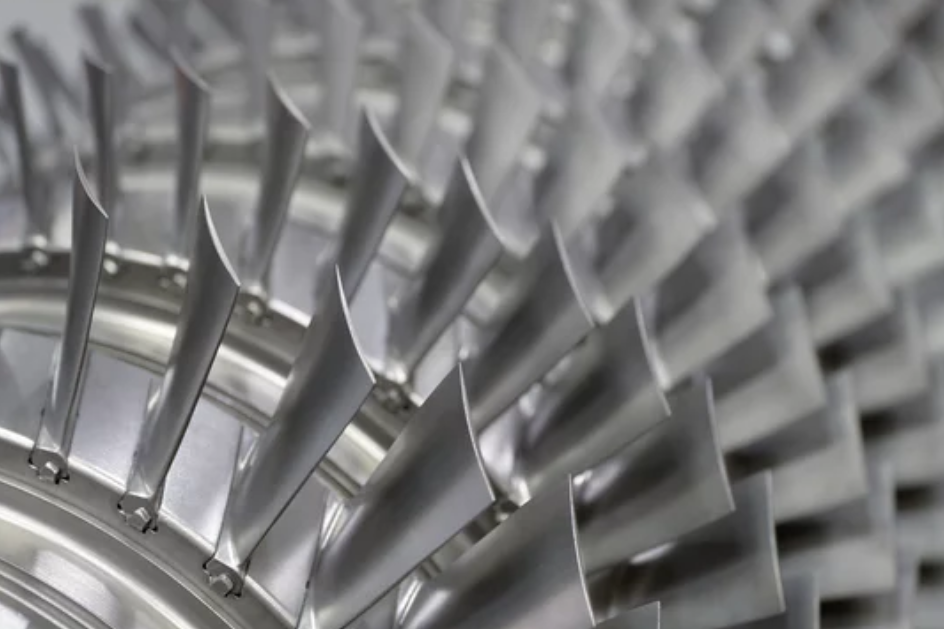
Design is therefore part of the tolerance plan. Neway reviews geometry before tooling to identify where a part may warp, bow, shrink unevenly, or need secondary machining. This review is especially important for gears, cams, thin-wall brackets, latch inserts, medical parts, connector features, and precision mechanisms.
Design factor | Dimensional effect | Typical MIM risk | RFQ detail to provide |
|---|---|---|---|
Wall thickness balance | Affects filling, debinding, and shrinkage uniformity. | Warping, sink-like distortion, profile drift | Wall section map and critical thickness areas |
Part symmetry | Helps the part shrink and support more evenly. | Bowing or uneven movement during sintering | Functional orientation and assembly direction |
Holes, slots, and bosses | Can shift or distort during shrinkage. | Ovality, position error, weak transition areas | Fit requirement, mating part, measurement method |
Datum and critical dimension placement | Controls how the part is measured and assembled. | Inspection results may not match final function. | Datum scheme, CTQ list, assembly drawing |
How do wall thickness, symmetry, and transitions affect shrinkage?
Balanced wall thickness helps molding and sintering behave consistently. Thick sections next to thin ribs can shrink differently and create local distortion. Long unsupported walls and large flat areas can bow during thermal processing. Smooth transitions can reduce stress concentration and improve process stability.
Symmetry can help the part shrink more evenly, but functional parts are not always symmetrical. When the design must be asymmetric, Neway reviews support surfaces, sintering orientation, wall transitions, and potential secondary operations. The goal is to identify accuracy risks before the tool is made.
Buyers should mark dimensions that cannot move, such as sealing faces, gear mesh datums, latch faces, and connector interfaces. Neway can then decide whether geometry changes, support features, or machining allowance are needed.
How do holes, slots, ribs, bosses, and undercuts affect accuracy?
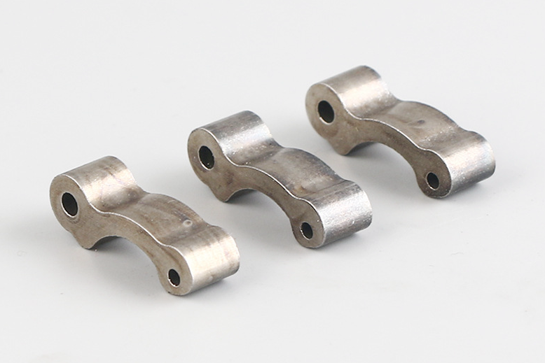
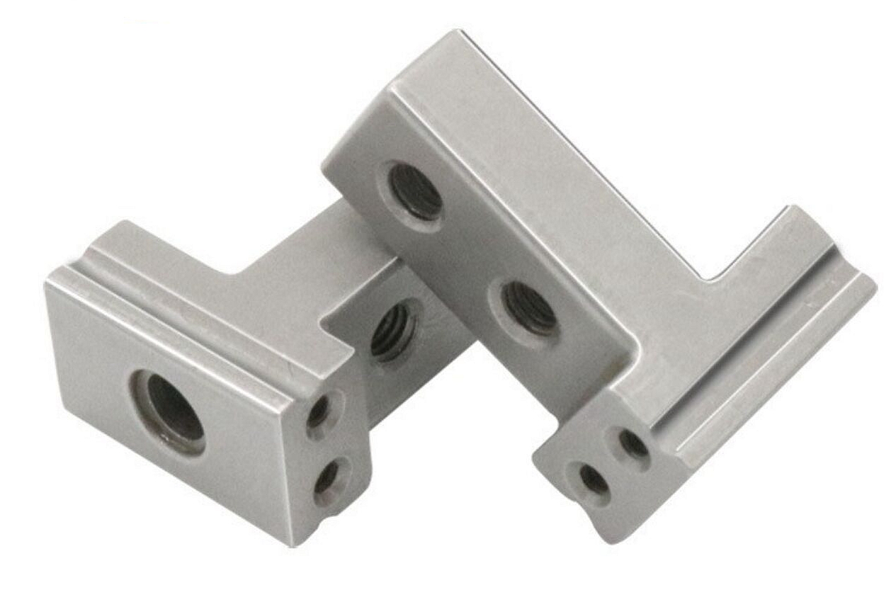
Small holes, long slots, thin ribs, isolated bosses, and undercuts are common reasons buyers choose MIM, but these features also create dimensional risk. Holes can become oval, slots can shift, ribs can distort, and bosses can pull nearby geometry during shrinkage.
MIM can form complex features, but each feature should be reviewed for molding flow, debinding access, sintering support, ejection, and inspection. A feature that looks simple in CAD may be difficult to measure or support after molding and sintering.
For tight features, Neway may recommend adding radius, adjusting wall balance, changing gate location, modifying boss design, or leaving machining allowance. The RFQ should identify which features are functional and which features are only for weight reduction or packaging.
How should datums and critical dimensions be placed?
Datums should reflect how the MIM part works in the assembly. If a part is measured from a surface that does not control assembly, the inspection report may not predict final fit. Neway reviews the drawing datum scheme with the mating part, fixture concept, and functional load path.
Critical dimensions should be limited to features that control fit, motion, sealing, wear, or safety. Applying tight tolerance to every feature increases cost and may distract from the dimensions that matter. Buyers should identify CTQ dimensions, gauge requirements, and any functional tests needed for approval.
Critical feature | Datum concern | Accuracy risk | Possible control route |
|---|---|---|---|
Bore or shaft fit | Datum should match mating shaft or pin. | Fit error after sintering or finishing | Machining, reaming, gauge inspection |
Gear tooth profile | Gear datum should match assembly axis. | Noise, backlash, uneven wear | Profile review and functional gear check |
Latch or cam contact face | Datum should match load direction. | Timing, force, or wear variation | Local finishing and CMM or fixture check |
Flatness or sealing face | Datum should match sealing or mounting interface. | Leakage, uneven contact, assembly gap | Support strategy, machining, flatness inspection |
What gate, ejection, support, and secondary operation issues should be considered?
Gate location affects filling, green density, weld lines, and gate vestige. Ejection affects green part deformation and visible marks. Sintering support affects flatness, straightness, and profile retention. These tooling and process choices should be reviewed with the drawing, not decided after the part fails inspection.
Secondary operations may be needed when the required tolerance cannot be held as-sintered. CNC machining, reaming, tapping, grinding, sizing, coining, polishing, or coating control may be added for selected features. These operations should be planned before tooling so enough material and access are available.
What RFQ and DFM data helps improve MIM dimensional accuracy?
A useful RFQ should include 3D models, 2D drawings, datum scheme, critical dimensions, material grade, annual volume, wall thickness, assembly drawing, mating parts, heat treatment, surface finish, machined features, coating limits, and inspection method. Buyers should also state which features may be redesigned and which features are fixed by the product architecture.
Neway can then perform DFM review before tooling, identify shrinkage-sensitive features, recommend geometry changes, and separate as-sintered dimensions from dimensions that need secondary finishing. Dimensional accuracy improves when design, tooling, process, and inspection are planned together.
Related FAQs
What tolerances can precision metal injection molding services typically achieve?
How are tight-tolerance components controlled during the MIM shrinkage process?
What quality inspection methods are used for tight-tolerance MIM components?
What are the applications of thin-walled MIM parts across industries?
What tooling considerations are important for high-volume MIM production?