Can OEM metal injection molding services produce complex stainless steel parts with custom features?
Yes, OEM metal injection molding (MIM) services can produce complex stainless steel parts with custom features when the part geometry, stainless grade, tooling plan, sintering shrinkage, secondary operations, and inspection method are matched correctly. The practical RFQ problem is to decide which ribs, slots, holes, teeth, bosses, threads, datums, and cosmetic surfaces can be molded directly and which features should be machined or finished after sintering.
Which custom features can stainless steel MIM form?
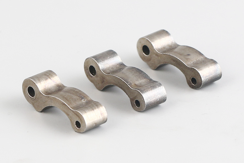
Stainless steel MIM can form many small complex features near net shape, including ribs, bosses, slots, external profiles, teeth, thin sections, grooves, small holes, undercut-like geometry with suitable tooling, and integrated mounting features. This capability is useful for OEM components used in locking systems, medical devices, electronics, power tools, and compact mechanical assemblies.
MIM is especially useful when the custom feature set would require many CNC machining operations if the part were cut from stainless steel bar or billet. The process can mold several features into one compact part body, which can reduce part count and reduce repeated machining time when production volume supports tooling.
Custom Stainless Steel MIM Feature | Why MIM Can Be Useful | RFQ Detail Buyers Should Define |
|---|---|---|
Ribs and bosses | Can be molded into the part body without separate assembly | Wall thickness, draft, support, and functional load |
Slots and grooves | Can reduce repeated milling when geometry is suitable | Slot width, depth, end radius, and inspection method |
Small holes | May be molded when size, depth, and location are practical | Hole diameter, tolerance, depth, and whether reaming is allowed |
Teeth and latch features | Can support compact mechanical engagement | Contact surface, wear requirement, hardness, and profile inspection |
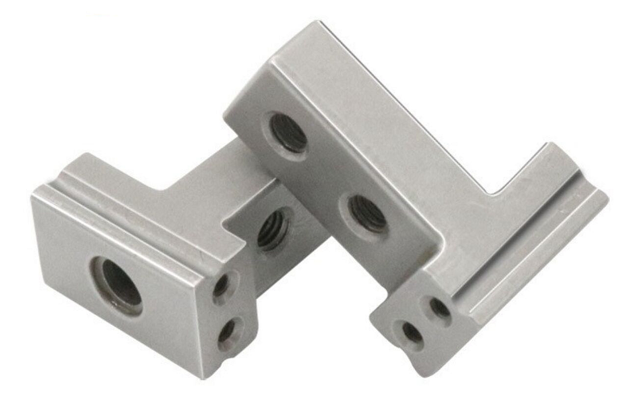
Threads and bores | Can be formed or post-machined depending on tolerance and function | Thread class, bore tolerance, datum relation, and gauge check |
Cosmetic surfaces | Can be finished after sintering when appearance matters | Visible zone, finish texture, and acceptance criteria |
When should threads, bores, and datums be molded or machined?
Threads, bores, and datums should be molded when the tolerance, surface condition, and functional load can be achieved economically by the MIM route. They should be machined after sintering when the feature controls assembly fit, sealing, rotation, threaded engagement, or a precise datum relationship that the as-sintered process cannot reliably hold.
A practical design approach is to mold the complex stainless steel body and machine only the critical areas. For example, the main latch shape may be molded, while a bore is reamed, a thread is tapped, or a datum face is ground after sintering. This keeps MIM's near-net-shape benefit while protecting important fit features.
For tolerance planning, see secondary machining for metal injection molded components and how MIM and machining differ for complex internal parts.
How do wall thickness, ribs, holes, and undercuts affect MIM tooling?
Wall thickness, ribs, holes, and undercuts affect MIM tooling because the mold must fill the feature, release the green part, and support stable shrinkage during sintering. Thin walls can increase fill and distortion risk. Deep ribs and dense features can affect feedstock flow. Small holes and slots can require careful mold steel design. Undercut-like features may require slides, inserts, or a design change.
The buyer should provide the 3D model and 2D drawing early so Neway can review mold parting, gate location, ejection, feature support, and inspection access. Tooling decisions made before sampling strongly affect whether complex features can repeat in production.
For design and tooling context, see design factors that affect dimensional accuracy in precision MIM parts and tooling considerations for high-volume MIM production.
How do stainless grade, shrinkage, and sintering affect complex features?
Stainless steel grade affects custom feature performance because 17-4 PH, 304, 316L, 420, 430, 430L, and 440C have different strength, corrosion resistance, hardness, magnetic response, and heat treatment behavior. A grade used for a medical component may not be the same as a grade used for a wear-loaded latch or power tool feature.
Shrinkage and sintering affect complex features because the molded part becomes smaller during thermal processing. Uneven wall thickness, heavy sections, delicate ribs, and asymmetrical geometry can shift dimensions or create distortion if the process is not controlled. The supplier must account for shrinkage in tooling and verify the result during sampling.
For material selection, see stainless steel grades used in OEM MIM services. For shrinkage control, see how tight-tolerance components are controlled during the MIM shrinkage process.
What inspection and secondary operations support custom stainless MIM features?
Complex stainless steel MIM features may need CMM inspection, optical profile inspection, gauges, thread checks, surface review, hardness testing, or material reports depending on the drawing. Features that control assembly, wear, alignment, or sealing should be inspected more carefully than cosmetic or hidden surfaces.
Secondary operations may include tapping, reaming, milling, grinding, polishing, passivation, electropolishing, heat treatment, or coating. These operations should be linked to specific features and requirements. For example, a threaded hole may need tapping and gauge verification, while a visible stainless surface may need polishing or passivation.
Related guidance includes inspection methods for tight-tolerance MIM components and surface finishes for custom stainless steel MIM parts.
Feature Type | Possible Post-Sintering Operation | Inspection Focus |
|---|---|---|
Threaded hole | Tapping or thread forming when required | Thread gauge, burr review, and depth |
Precision bore | Reaming, boring, or honing when required | Diameter, roundness, position, and surface condition |
Datum face | Milling or grinding when required | Flatness-related requirement and datum relationship |
Profile or tooth feature | Local finishing or heat treatment review | Profile shape, contact surface, hardness, and wear risk |
Visible surface | Polishing, brushing, passivation, or coating | Appearance, texture, corrosion exposure, and masking |
What RFQ details help Neway quote complex stainless steel MIM parts?
Neway can quote complex stainless steel MIM parts more accurately when the RFQ includes the 3D CAD file, 2D drawing, stainless grade or property target, annual volume, critical features, custom feature list, thread and bore requirements, GD&T, surface finish, heat treatment, secondary operations, inspection report needs, and mating part information.
Buyers should state which features are flexible and which features are not. If a small hole can be changed, Neway may recommend a more mold-friendly size. If a datum must be tight, Neway may recommend machining and CMM inspection. If a surface is cosmetic, Neway needs visible-area criteria and finish expectations. Clear RFQ details make it easier to decide whether the feature should be molded, machined, finished, or redesigned before tooling.
Related FAQs
Why are stainless steel parts a good fit for metal injection molding?
Which stainless steel grades are commonly used in OEM metal injection molding services?
What surface finishes are available for custom stainless steel MIM parts?
What should OEM buyers provide when requesting a quote for custom stainless steel MIM parts?
Can secondary machining improve tolerances for metal injection molded components?
Which design factors affect dimensional accuracy in precision MIM parts?
What tooling considerations are important for high-volume MIM production?