3D Scanning Measuring Instrument Custom Parts Quality
3D Scanning Custom Parts Quality RFQ Decision: This article explains how buyers can specify 3D scanning measurement for custom parts made by CNC machining, injection molding, precision casting, sheet metal fabrication, prototyping, and assembly validation routes. The practical RFQ problem is deciding when full-surface scan data, CAD comparison, deformation analysis, reverse engineering data, inspection reports, and buyer acceptance criteria are needed beyond ordinary dimensional checks.

When Should Buyers Request 3D Scanning Measurement?
Buyers should request 3D scanning when a custom part has complex freeform surfaces, large-area shape deviation, warpage risk, prototype iteration needs, reverse engineering requirements, or many surface points that are hard to capture with point-by-point measurement.
The engineering reason is that 3D scanning creates a digital surface dataset that can be compared with CAD geometry or a reference part. This is useful when the buyer needs a shape-deviation map, not only a small list of critical dimensions.
For quotation, the buyer should define the scanning purpose, part size, material surface condition, required areas, CAD reference, report format, tolerance zones, sampling quantity, and whether the scan is for prototype feedback, production inspection, or failure investigation.
What Does 3D Scanning Measure In Custom Parts?
3D scanning measures visible surface geometry. It can support CAD-to-part comparison, part-to-part comparison, deformation review, reverse engineering, assembly fit checks, and design iteration feedback.
3D Scanning Entity | Buyer Should Specify | Inspection Result Supported |
|---|---|---|
Surface deviation | CAD reference, color-map requirement, tolerance bands, and scan areas | Shows where the part surface differs from the model. |
Warping or deformation | Free-state or constrained state, datum alignment, and comparison target | Helps review molded, cast, formed, or welded part distortion. |
Prototype feedback | Design revision, functional surfaces, and change-request focus | Supports design iteration before tooling or production release. |
Reverse engineering | Required file output, surface quality, and downstream CAD use | Creates measurement data for rebuilding or comparing existing parts. |
3D scanning should be tied to the buyer's decision. A full scan is most valuable when the resulting data will guide design, tooling, assembly, or corrective action.
How Does 3D Scanning Compare With CMM And Optical Comparator?
3D scanning is strong for dense surface data and shape visualization. CMM dimensional inspection is stronger for defined datums, GD&T relationships, and high-confidence point measurement of critical features. Optical comparator profile inspection is useful for visible 2D profiles, edges, radii, and silhouettes.
Inspection Method | Best Fit | Buyer Decision Point |
|---|---|---|
3D scanning | Freeform surfaces, prototype comparison, deformation maps, and reverse engineering | Use when many surface points or CAD deviation maps are needed. |
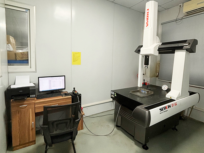
CMM inspection | Critical datums, hole position, flatness, true position, and GD&T reports | Use when measured features must be tied tightly to the drawing datum scheme. |
Optical comparator | 2D profile, small edge, slot, radius, and silhouette inspection | Use when a visible profile can be compared efficiently. |
Buyers may need more than one method. The RFQ should identify which inspection question each method answers.
Which Manufacturing Processes Benefit From 3D Scanning?
3D scanning can support several custom parts processes, especially when a part has complex surface geometry or a risk of distortion.
Manufacturing Process | 3D Scanning Use | RFQ Detail Needed |
|---|---|---|
CNC machining | Freeform surfaces, 5-axis features, prototype comparison, and fixture validation | CAD model, critical surfaces, datum alignment, and report format. |
Injection molding | Warpage, shrinkage, sink-related deformation, and assembly fit feedback | Material, mold trial stage, free-state measurement, and functional surfaces. |
Precision casting | Casting distortion, machining allowance, surface comparison, and pattern correction | Casting route, datum targets, post-machining state, and comparison model. |
Sheet metal fabrication | Formed surfaces, enclosure shape, welded distortion, and assembly gaps | Material thickness, bend sequence, constrained-state condition, and assembly datum. |
The buyer should state whether the scan is required before tooling correction, after machining, before shipment, or after assembly. Timing affects what the scan data can improve.
How Should Buyers Define Scan Data And Reports?
The RFQ should define scan data output before inspection starts. Buyers may need color maps, deviation tables, STL mesh data, point clouds, feature measurements, annotated screenshots, or a pass-fail summary.
Alignment method is important. Best-fit alignment, datum alignment, fixture alignment, and assembly-position alignment can produce different interpretation. The buyer should specify which alignment supports the engineering decision.
Surface preparation should also be discussed. Reflective, transparent, dark, oily, or very small features may require extra preparation or a different inspection method. The supplier should confirm whether surface condition affects scan quality.
How Should 3D Scanning Feed Process Improvement?
3D scanning results should feed design, tooling, fixture, machining, molding, casting, or welding decisions. A scan report is most useful when the buyer and supplier agree how deviation data will be reviewed and acted on.
The scan can support a PDCA control system: plan the measurement, produce the part, check the surface data, and act on the deviation pattern. If the color map shows recurring distortion, the action may be tooling correction, fixture change, process adjustment, or drawing review.
For prototype programs, scan data can help the buyer decide whether the design is ready for tooling, whether a tolerance is practical, or whether a manufacturing route needs to change.
What Should Buyers Include In A 3D Scanning RFQ?
A complete 3D scanning RFQ should include the part drawing, CAD model, part material, surface condition, scan purpose, required areas, alignment method, tolerance bands, output file format, report format, sampling quantity, and acceptance criteria.
The buyer should also state whether the scan is for first article, prototype feedback, production release, reverse engineering, incoming inspection, or corrective action. Each use case changes the level of detail needed.
This structure helps the supplier quote 3D scanning work accurately and gives the buyer usable measurement data for the actual custom parts quality decision.
Related FAQs