How Does Neway Assist in Designing and Prototyping MIM Parts?
Neway can assist in designing and prototyping Metal Injection Molding parts by reviewing MIM manufacturability, material selection, tooling requirements, shrinkage control, sintering risk, secondary operations, and inspection needs. The practical RFQ problem is deciding what design evidence a buyer needs before moving a small complex metal part from concept, CAD model, or prototype sample into MIM tooling and production planning.
How can Neway assist in MIM part design and prototyping?
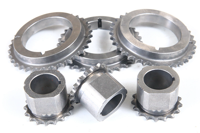
Neway can assist by reviewing whether the part geometry, material, wall thickness, small features, holes, threads, datum surfaces, and production quantity fit the Metal Injection Molding route. This review helps buyers understand whether MIM is suitable or whether CNC machining, casting, stamping, or another prototyping process should be considered first.
The support should be treated as a manufacturing review, not a replacement for the buyer's product engineering responsibility. The buyer still needs to define function, load, environment, assembly interfaces, inspection requirements, and final acceptance criteria.
MIM design support area | Manufacturing entity reviewed | Buyer decision supported |
|---|---|---|
Process suitability | MIM route, CNC machining alternative, casting alternative, production volume | Decide whether MIM is the right manufacturing process |
Material selection | Stainless steel, tool steel, magnetic alloy, low-alloy steel, specialty MIM materials | Match material behavior to function and cost target |
DFM review | Wall thickness, ribs, bosses, holes, slots, undercuts, gate location | Reduce molding, debinding, and sintering risk |
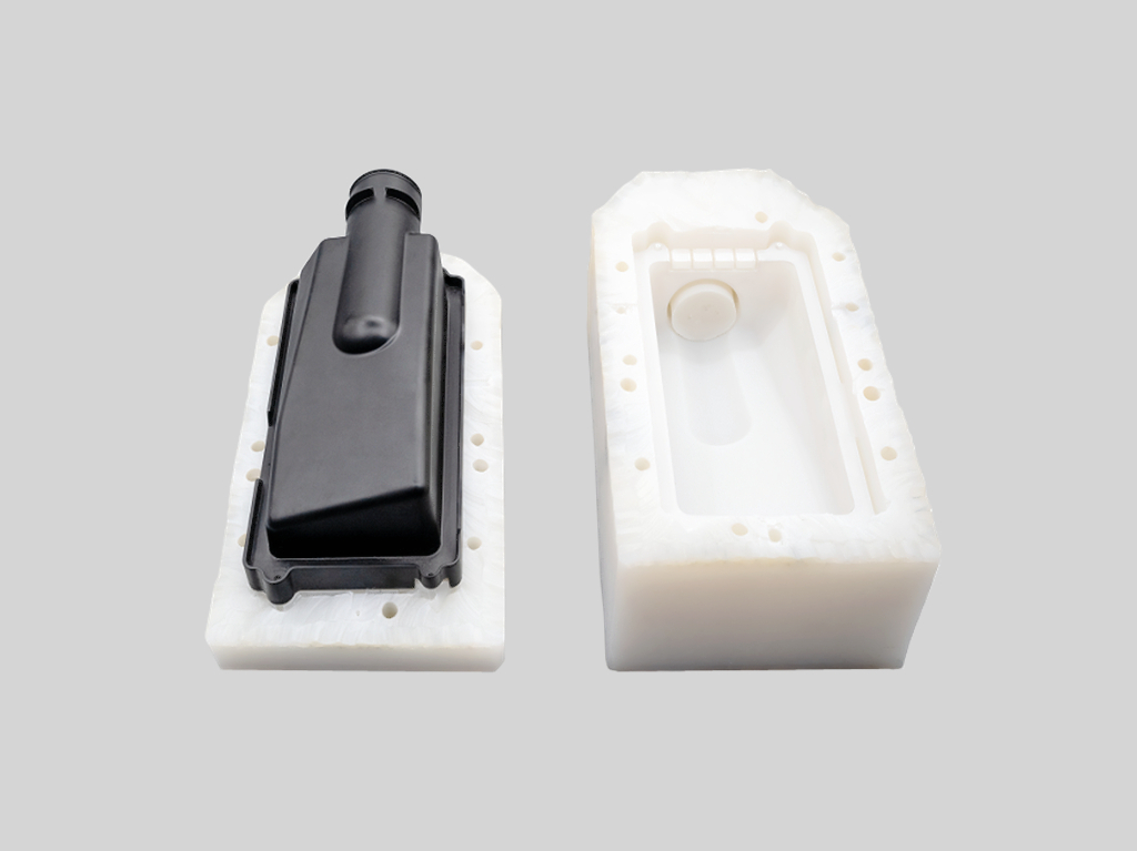
Tooling planning | Mold cavity, parting line, gate, ejector, shrinkage compensation | Understand tooling feasibility before committing to tooling |
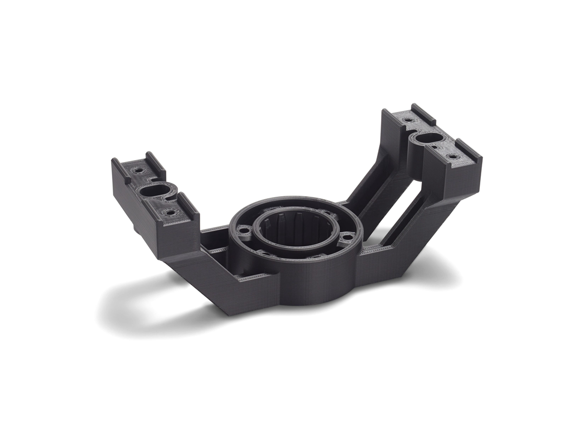
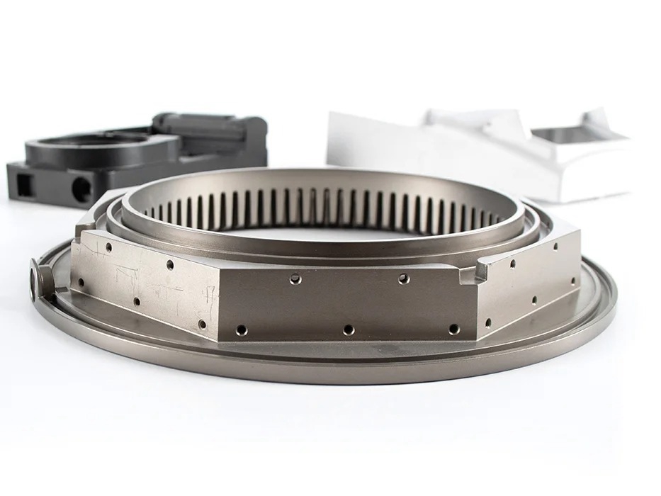
Prototype planning | CNC prototype, 3D printed model, MIM sample, functional test part | Select the sample route that answers the current engineering question |
Sintering control | Debinding, sintering support, distortion risk, density, shrinkage | Plan dimensional and material validation |
Secondary operations | Machining, tapping, heat treatment, polishing, coating, passivation | Identify features that may need post-sintering control |
Inspection planning | CMM checks, gauges, visual inspection, material testing, functional testing | Define acceptance criteria for samples and production parts |
What should be reviewed during MIM DFM before tooling?
MIM DFM should review the features that affect feedstock flow, mold filling, debinding, sintering, shrinkage, and ejection. Thin walls, long slots, deep holes, sharp transitions, isolated bosses, fine text, and fragile features can increase manufacturing risk if the geometry is not adjusted for the MIM process.
The DFM review should also identify which surfaces are functional. A small MIM gear, latch, hinge, connector, medical instrument component, firearm component, sensor part, or wearable device part may have several features that look similar in CAD but carry very different inspection importance.
Buyers should provide both the 3D model and 2D drawing. The 3D model shows geometry. The 2D drawing should identify tolerances, datums, material, surface finish, heat treatment, and inspection requirements. When these documents conflict, the quotation can become unreliable.
How do material, tooling, and shrinkage planning affect MIM prototypes?
Material planning affects MIM prototype behavior because each alloy and powder feedstock has different molding, debinding, sintering, shrinkage, and final property behavior. Buyers should state the required alloy grade and any approved substitute material before sampling.
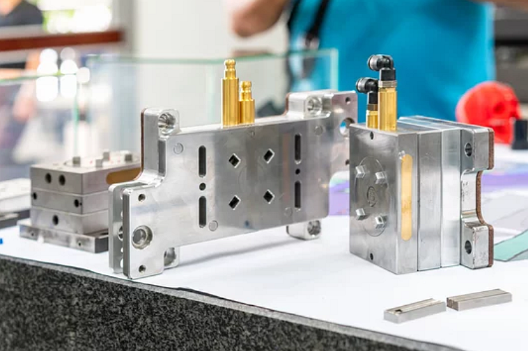
Tooling planning affects the prototype because the MIM mold must compensate for sintering shrinkage. Gate location, parting line, ejector layout, wall thickness, and mold cavity compensation all influence whether the sintered sample can meet the drawing requirements.
Shrinkage planning should focus on the dimensions that matter most. If the buyer needs a tight bore, threaded hole, sealing face, flat datum, or bearing surface, the RFQ should identify whether the feature must be controlled as-sintered or finished by secondary machining after sintering.
Which prototype route should buyers use before MIM production?
The prototype route should match the engineering question. CNC machining may be useful for early fit checks and functional metal testing. 3D printing may be useful for concept shape review. MIM sampling may be needed when the buyer must validate molded geometry, sintered material behavior, shrinkage, surface condition, and production-like small metal features.
A buyer should not assume that one prototype route answers every question. A CNC prototype may confirm assembly, but a CNC prototype will not show MIM shrinkage. A 3D printed model may confirm packaging, but a 3D printed model will not confirm sintered metal density. A MIM sample can provide process-specific evidence, but it needs tooling and process planning.
When the product is still changing, early prototype routes can reduce risk before MIM tooling. When the design is near final, MIM samples and inspection data become more important for production readiness.
What inspection and secondary operations should be planned for MIM prototypes?
MIM prototype inspection should match the functional risk. Common inspection needs may include CMM measurement, pin gauges, thread gauges, visual inspection, surface finish checks, density review, hardness testing, material confirmation, or functional assembly testing.
Secondary operations may include CNC machining, tapping, sizing, heat treatment, polishing, bead blasting, coating, passivation, or plating. These operations should be stated before quotation if the part requires controlled threads, tight bores, sealing faces, bearing surfaces, cosmetic surfaces, or corrosion resistance.
For regulated or safety-related uses, final validation remains the buyer's responsibility. Manufacturing samples and inspection data can support the decision, but the buyer should define the final test plan and approval route.
What should buyers provide when requesting MIM design and prototyping support?
A strong MIM design and prototyping RFQ should include the 3D CAD file, 2D drawing, target alloy, annual volume estimate, prototype purpose, functional surfaces, critical dimensions, tolerance notes, surface finish requirements, heat treatment, secondary operations, inspection needs, and any application restrictions.
Buyers should also explain the decision they need the prototype to support. The decision may be process selection, material validation, assembly fit, shrinkage control, cost comparison, production readiness, or customer approval. That decision helps align DFM review, sample route, tooling scope, and inspection effort.
The practical answer is that Neway's role in MIM design and prototyping is to connect design requirements with manufacturable MIM process steps. The buyer gets the most useful support when the RFQ clearly states the part function, the manufacturing risk, and the decision that must be made after prototype review.
Related FAQs