Metal Injection Molding Service | Custom MIM Aerospace Parts
This article explains metal injection molding service evaluation for custom aerospace-related MIM parts, including titanium, stainless steel, nickel alloy, cobalt alloy, and other small complex metal components. The practical RFQ problem is deciding whether MIM can meet the part geometry, material grade, shrinkage control, sintered density, secondary machining, heat treatment, surface finish, and inspection evidence required before a buyer releases a prototype or production quote.
The short answer is that MIM can be a strong candidate for small complex metal parts when machining would remove too much material or when die casting and investment casting cannot match the geometry, material, or production plan. For regulated aerospace programs, buyers should define drawing requirements, material documentation, inspection evidence, and approval responsibility in the RFQ; MIM suitability must be validated against the project specification rather than assumed from the process name.
Neway provides related metal injection molding support when buyers need route selection for small complex metal components before tooling.
MIM Service RFQ Decision for Custom Aerospace-Related Metal Parts
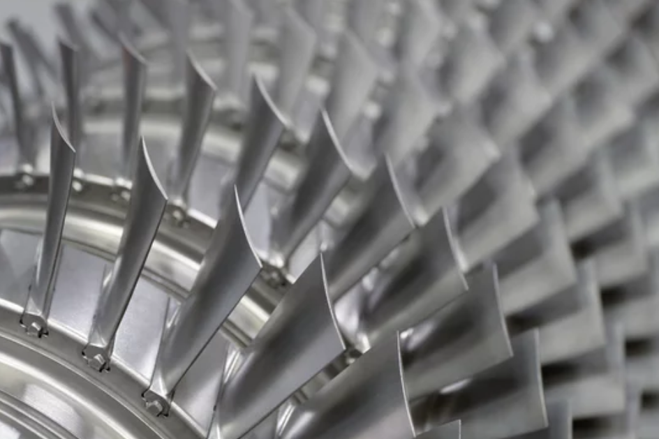
MIM should be evaluated when the component is small, complex, repeated in quantity, and difficult to machine efficiently from bar or billet. Typical RFQ candidates include brackets, levers, clips, housings, turbine blade-shaped samples, fastener hardware, connector components, locking features, micro-gear elements, and heat-exposed internal structures.
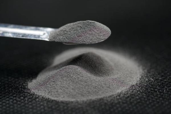
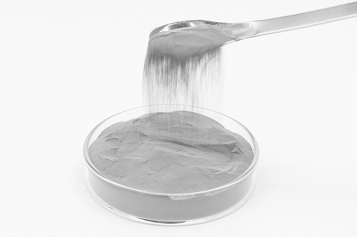
The manufacturing reason is that MIM combines metal powder with a binder system, molds the feedstock, removes the binder, and sinters the part to reach the final metal structure. This route can form fine details and internal features near net shape, but the final part depends on feedstock control, mold design, debinding, sintering shrinkage, secondary machining, and inspection.
Buyer Question | MIM Service Answer | RFQ Information Needed |
|---|---|---|
Is the part geometry suitable? | MIM fits small complex metal parts with repeated details, thin walls, small bosses, and internal features | STEP file, 2D drawing, wall sections, holes, slots, ribs, datums, and critical dimensions |
Which material family is needed? | Titanium alloys, stainless steels, nickel alloys, cobalt alloys, tungsten alloys, and tool steels may be reviewed | Material grade, heat exposure, corrosion exposure, magnetic need, wear requirement, and allowed alternatives |
Which dimensions are critical? | Sintering shrinkage and secondary machining strategy determine final dimensional control | CTQ dimensions, datum surfaces, bores, threads, sealing faces, and gauge requirements |
Which evidence is required? | Inspection scope depends on the part function and buyer specification | Dimensional report, material report, density check, visual criteria, functional test, and sample plan |
How Metal Injection Molding Produces Small Complex Metal Components
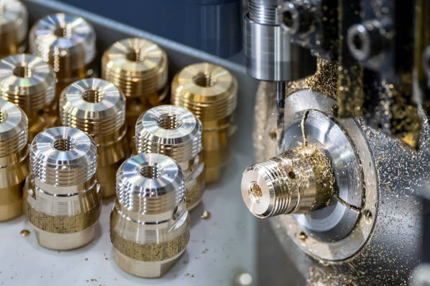
The MIM process begins with fine metal powder and binder feedstock. The feedstock is injection molded into a green part, then debound to remove binder and sintered to densify the metal. After sintering, the part may receive heat treatment, sizing, CNC machining, grinding, polishing, coating, passivation, or assembly depending on the drawing.
The engineering reason MIM can help is that the molded route can create near-net-shape features before the metal is fully dense. A complex machined part may require multiple setups and high material waste, while MIM can form repeated small geometry in the mold. The trade-off is that shrinkage must be designed into tooling and process controls.
For general process background, see what metal injection molding is and how it works.
MIM Materials for High-Temperature, Corrosion, Wear, and Lightweight Requirements
Material selection should be tied to the part function. Titanium MIM materials may be reviewed when lightweight strength and corrosion behavior matter. Stainless steel MIM grades such as 17-4 PH, 316L, 420, 430, or 440C may be reviewed for corrosion, wear, magnetic behavior, or hardness targets. Nickel alloys and cobalt alloys may be reviewed for demanding heat, wear, or corrosion environments. Tungsten alloys may be reviewed when high density or special balance requirements matter.
The RFQ implication is that the buyer should specify the required grade and the reason for that grade. If the drawing allows supplier-recommended alternatives, the RFQ should state which properties can change and which properties are fixed. MIM material selection is not only a list of metals; the selected metal powder, sintering cycle, heat treatment, and secondary finishing all influence the delivered component.
MIM Material Family | Common Buyer Requirement | Part Features to Review | Related Material Page |
|---|---|---|---|
Titanium alloy | Lightweight metal parts, corrosion behavior, and high strength-to-weight needs | Thin walls, small radii, machined datums, and sintering distortion risk | |
Stainless steel | Corrosion resistance, hardness, wear behavior, and general mechanical performance | Threads, bores, sliding faces, passivation, and heat treatment response | |
Nickel alloy | Heat exposure, corrosion resistance, and demanding service environments | Thermal distortion, sintering control, heat treatment, and functional surfaces | |
Cobalt alloy | Wear resistance, corrosion behavior, and high-performance metal part requirements | Edge condition, polished surfaces, density, and dimensional stability |
Mold Design, Shrinkage, Sintering, and Secondary Machining Risks
MIM tooling must anticipate shrinkage from the molded green part to the final sintered part. Gate location, wall thickness, flow length, parting line, ejector placement, and sintering support can all affect dimensional control and cosmetic condition.
The main design risks are thick-to-thin transitions, isolated heavy sections, sharp internal corners, unsupported long spans, tiny holes, deep blind features, and surfaces that require tight final dimensions. Some features can be molded close to final size, while other features may need post-sintering machining or grinding.
The RFQ implication is that buyers should mark the dimensions that truly control function. Over-tight requirements on every surface can raise cost without improving performance. For a detailed tooling discussion, see MIM mold design considerations.
Inspection Evidence for Aerospace-Related MIM Parts
Inspection evidence should match the part function and buyer specification. Dimensional inspection may include CMM reports, optical measurement, pin gauges, thread gauges, and fixture checks. Material and process evidence may include density checks, hardness checks, heat-treatment review, microstructure review, or material reports where required by the buyer.
For aerospace-related parts, the RFQ should state the drawing revision, acceptance criteria, sampling plan, required documentation, and responsibility for qualification. MIM can support complex metal component manufacturing, but the buyer and supplier must agree on validation evidence before production release.
The manufacturing implication is that inspection should be built into the process plan, not added after a part fails assembly. Critical features, mating surfaces, holes, threads, and heat-exposed regions should be identified before tooling design.
When MIM, CNC Machining, Investment Casting, or Die Casting Fits Better
Choose MIM when the part is small, complex, repeated in quantity, and made from a metal powder system that fits the performance requirement. Choose CNC machining when the part quantity is low, the geometry is simple, or the key surfaces require direct machining from wrought stock. Choose investment casting when the part is larger, has a different alloy or geometry need, or does not justify MIM feedstock and tooling. Choose die casting when aluminum or zinc alloy, thin-wall geometry, and production volume fit pressure casting.
The buyer decision should compare material, geometry, annual demand, tolerance, machining allowance, mechanical requirement, and inspection evidence together. Neway's comparison article on MIM vs CNC machining, die casting, and investment casting can help frame this process choice.
RFQ Checklist for Custom MIM Aerospace-Related Parts
A useful MIM RFQ should allow the supplier to evaluate material, molding, shrinkage, sintering, secondary operations, and inspection evidence before quoting. The stronger the RFQ package, the easier it is to separate true MIM risks from normal design review items.
RFQ Item | Why It Matters for MIM | Recommended Buyer Input |
|---|---|---|
Material grade | Metal powder, sintering, heat treatment, and performance depend on grade selection | Required grade, allowed alternatives, operating environment, and material evidence needed |
3D model and drawing | Mold flow, shrinkage compensation, and secondary machining depend on full geometry | STEP file, 2D drawing, revision, wall thickness, holes, ribs, bosses, and datums |
Critical dimensions | Final tolerance may require secondary machining or special inspection | CTQ dimensions, gauges, threads, bores, sealing faces, mating surfaces, and flatness notes |
Mechanical and thermal requirement | Heat treatment, density, and material selection can change the process route | Load condition, temperature exposure, wear surface, corrosion exposure, and functional test |
Production demand | Tooling, cavity strategy, and inspection level depend on quantity and revision stability | Prototype quantity, annual demand, ramp schedule, revision risk, and packaging requirement |
Inspection evidence | Regulated or critical parts need agreed acceptance evidence before release | Dimensional report, material report, hardness check, density check, visual criteria, and sample plan |
Related FAQs