Precision Mechanical Components for High-Performance Tools
Power Tool Precision Mechanical Component RFQ Decision: This article explains how buyers can specify metal injection molding, powder pressing molding, precision casting, and CNC machining prototyping for precision mechanical components used in high-performance tools. The part types include gears, shafts, transmission inserts, clutch parts, bearing features, structural brackets, and small mechanism parts. The practical RFQ problem is deciding which process route, material grade, heat treatment, secondary machining, and inspection evidence should be quoted before the buyer validates torque transfer, rotation accuracy, wear behavior, and assembly fit.
Precision mechanical components in power tools are not only small metal parts. A gear tooth, shaft datum, threaded insert, sliding latch, or clutch face can affect motor output, vibration, heat buildup, and maintenance risk. Buyers should define the component function before asking for a quote, because the same drawing can require different manufacturing controls when the part is used for torque transfer, alignment, impact absorption, or housing support.
Which Precision Mechanical Tool Parts Should Be Defined First?
The RFQ should start with the mechanical role of the part. A transmission gear needs tooth geometry, density control, wear surface definition, and heat treatment planning. A shaft needs concentricity, bearing surface finish, thread control, and datum machining. A clutch component needs impact resistance, edge condition, and contact surface control. A cast bracket or housing feature needs rib geometry, insert location, and machining allowance.
This classification helps the supplier quote the correct manufacturing route. A small mechanism part with complex undercuts may suit MIM. A sintered gear or bushing may suit powder pressing molding. A bracket with larger ribs or thicker walls may suit precision casting with machining. A prototype shaft or datum-critical feature may need CNC machining before production tooling is considered.
Precision Tool Component | Primary Manufacturing Concern | Likely Process Route | RFQ Evidence To Request |
|---|---|---|---|
Transmission gear | Tooth geometry, density, wear face, heat treatment | Powder pressing molding or MIM | Dimensional report and material or hardness record |
Precision shaft | Concentricity, bearing journal, thread, surface finish | CNC machining or machining after forming | CMM report and surface finish inspection |
Clutch or latch component | Small feature strength, edge condition, contact wear | MIM plus finishing or heat treatment | Critical dimension report and treatment record |
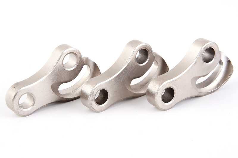
Housing bracket or frame insert | Rib strength, insert location, mounting datum, machining stock | Precision casting plus machining | First article inspection and fit review |
When Should MIM Be Used For Small Tool Mechanism Parts?
MIM should be reviewed when a high-performance tool component combines compact geometry, small features, and repeatable production needs. Trigger parts, locking features, small gears, levers, retainers, and clutch elements can be candidates when the design accepts sintering shrinkage control and when critical surfaces are identified before tooling. MIM is not only a shape-making process; MIM also requires feedstock selection, debinding, sintering, and possible secondary machining to meet functional requirements.
Buyers should state which surfaces are functional. A machined datum, reamed hole, thread, bearing face, or sliding contact may need post-sintering machining or finishing. For broader process background, buyers can compare MIM metal options, metal sintering behavior, and MIM mold design considerations before releasing production tooling.
When Does Powder Pressing Molding Fit Gears And Bushings?
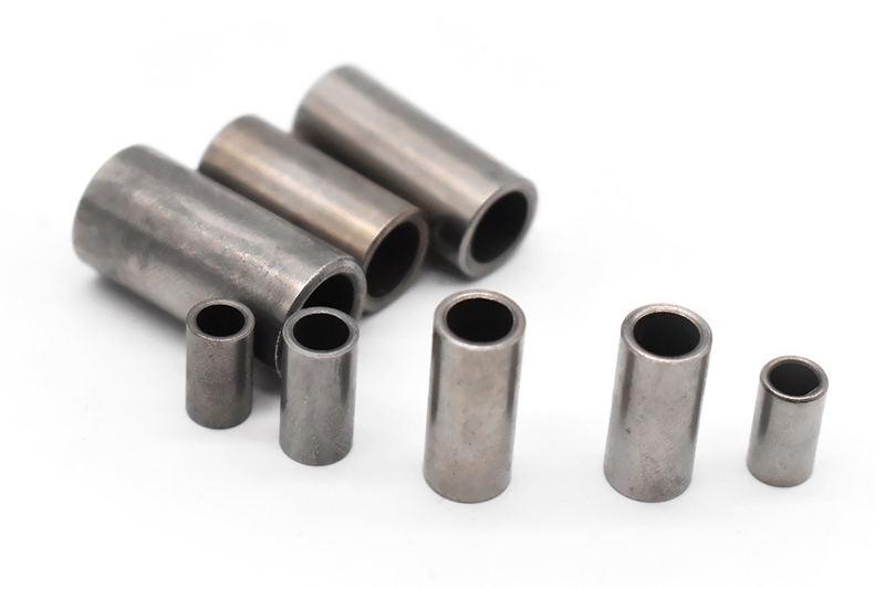
Powder pressing molding should be considered when the tool component is a gear, bushing, spacer, or powder metal part where production repeatability and material behavior are central to the decision. Powder pressing molding can support near-net shapes, sintered structures, and wear-focused mechanical features, but the buyer should define density expectations, tooth form risk, finishing needs, and lubricant or surface treatment requirements when they apply.
The RFQ should separate production-intent powder metal parts from appearance-only prototypes. A prototype gear machined from bar stock may check fit, but a powder pressed gear may behave differently in density, surface condition, and heat treatment response. Buyers can use powder metallurgy for sintered gears and bushings and powder compression molding materials and applications to frame the route comparison.
Which Materials And Heat Treatments Affect Tool Component Performance?
Material selection should be tied to the loading mode. Stainless steel such as 17-4 PH may be reviewed for strength and corrosion exposure. Alloy steels and tool steels may be reviewed for wear, impact, or hardened surfaces. Powder metal grades may be reviewed for sintered gears and bushings. Aluminum or zinc alloy casting materials may be reviewed for housings or structural brackets when weight and geometry drive the choice.
Heat treatment should be written as a process requirement, not a generic request for strength. A gear tooth, shaft journal, latch surface, and clutch face can require different hardness, case condition, or surface treatment. Buyers can reference heat treatment, nitriding, and black oxide coating when comparing manufacturing routes. The buyer should still validate the final torque, wear, and impact behavior in the finished tool assembly.
How Should Tolerances And Secondary Machining Be Quoted?
Tolerances should be assigned to functional features, not applied uniformly to the full drawing. A bearing journal, gear bore, shaft datum, threaded hole, motor interface, and mounting face may need tighter control than a non-contact exterior wall. When MIM, powder pressing molding, or precision casting creates the near-net shape, secondary machining may be needed only on datums, holes, sealing surfaces, threads, or bearing locations.
This decision affects cost, inspection, and lead-time planning. Buyers should mark critical-to-function features on the 2D drawing and identify which dimensions control assembly, rotation, backlash, torque transfer, or service access. For prototype work, CNC machining prototyping can support fit checks and early mechanical testing before a production route is confirmed.
RFQ Feature | Entity To Specify | Manufacturing Implication | Buyer Decision Supported |
|---|---|---|---|
Gear bore or shaft journal | Diameter tolerance, roundness, surface finish | May need CNC machining after MIM, PM, or casting | Assembly fit and rotation accuracy |
Threaded or reamed hole | Thread class, hole position, datum scheme | May need tapping, reaming, or fixture control | Fastener engagement and repeatable assembly |
Sliding latch or clutch face | Contact face, edge condition, hardness, coating | May need finishing, heat treatment, or wear review | Wear behavior and actuation feel |
Housing mounting datum | Flatness, hole pattern, machining stock | May need machining after precision casting | Motor alignment and tool assembly control |
What Inspection Evidence Should Support High-Performance Tool Parts?
Inspection should match the mechanical risk. CMM inspection can support datum schemes, hole position, gear location features, and housing interfaces. Hardness or material records can support heat-treated parts, tool steel components, and sintered gears. Surface finish inspection can support shafts, bearing locations, sliding features, and sealing faces. Industrial CT inspection may be useful when internal casting condition or density-related risk needs review.
The RFQ should state whether the report is needed for prototype samples, first article review, process validation, or recurring shipments. Buyers can reference CMM dimensional inspection and industrial CT defect inspection when the component risk justifies those records.
What Should Buyers Include In The Precision Tool Component RFQ?
A complete RFQ should include CAD files, 2D drawings, part function, mating parts, target process, material grade, heat treatment, surface treatment, critical dimensions, datum scheme, wear surfaces, prototype purpose, production stage, and inspection report requirements. For gears, buyers should include tooth geometry, bore control, density or material requirements, and heat treatment. For shafts, buyers should include bearing surfaces, concentricity, threads, and surface finish. For transmission inserts and clutch parts, buyers should include load path, contact surface, edge condition, and wear requirement.
Important buyer decisions should be stated directly. If MIM is being compared with powder pressing molding, the RFQ should show geometry, annual demand stage, functional surfaces, and secondary machining needs. If a prototype is being quoted, the RFQ should state whether the prototype is for fit, torque testing, wear testing, or production-route review. If the final tool assembly must pass buyer validation, the RFQ should state which process records and inspection reports will support that validation.
Related FAQs
What material and heat treatment requirements apply to gears in high-load tools?
How can precision manufacturing improve tool transmission efficiency and lifespan?
What tolerances can precision metal injection molding services typically achieve?
How are tight-tolerance components controlled during the MIM shrinkage process?
Can secondary machining improve tolerances for metal injection molded components?
What quality inspection methods are used for tight-tolerance MIM components?
What tooling considerations are important for high-volume MIM production?
What steps take special tool components from design to full-scale production?