What steps take special tool components from design to full-scale production?
Special tool components move from design to full-scale production through requirement definition, process selection, prototype validation, tooling development, pilot production, process stabilization, inspection planning, and volume manufacturing. This FAQ explains how Neway reviews metal injection molding, prototyping, aluminum die casting, plastic injection molding, heat treatment, surface finishing, and quality control for power tool gears, lock components, latches, inserts, housings, and compact mechanical assemblies. The practical RFQ problem is to define which design, material, tolerance, testing, and production-volume decisions must be approved before tooling and mass production begin.
What requirements should be defined before special tool component design?
Buyers should define function, load case, material requirement, tolerance, surface condition, assembly interface, validation method, and production volume before detailed design starts. These inputs decide whether the part should use MIM, machining, die casting, plastic injection molding, overmolding, or a hybrid route.
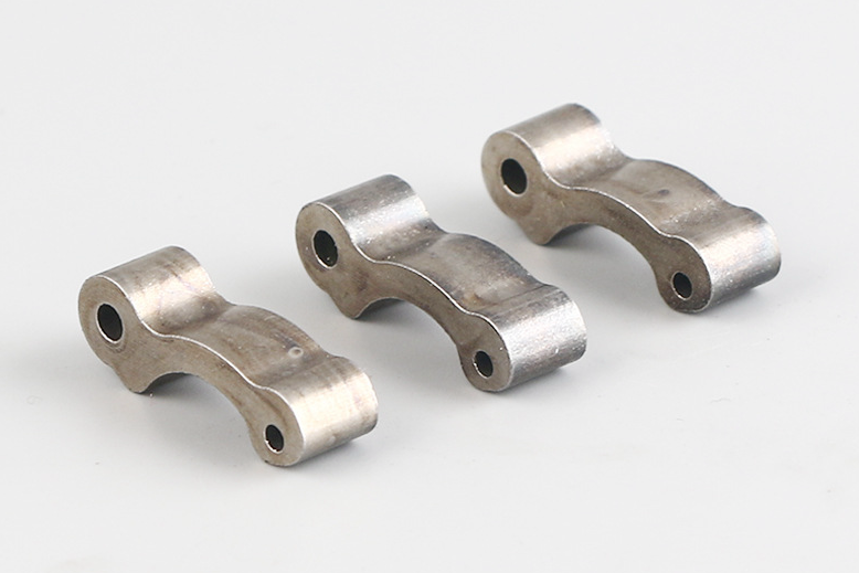
For special tool components, the RFQ should state torque, impact load, wear condition, drop requirement, fastener load, corrosion exposure, grip requirement, electrical insulation need, or thermal requirement when relevant. Metal injection molding may support small strong parts, gears, latches, inserts, sleeves, pawls, and complex lock components when geometry and volume justify tooling.
Project definition entity | Production decision affected | RFQ input needed |
|---|---|---|
Load and life requirement | Material grade, heat treatment, and validation method | Torque profile, impact load, cycle target, and pass criteria |
Geometry and tolerance | Process route, tooling design, shrinkage control, and inspection | 3D CAD, 2D drawing, datum scheme, and critical dimensions |
Surface and environment | Finishing, coating, corrosion protection, and wear testing | Surface finish, coating zones, exposure condition, and cleaning method |
Volume and ramp plan | Tooling investment, sampling plan, automation, and quality controls | Prototype quantity, pilot quantity, annual volume, and schedule priority |
How do prototypes reduce risk before tooling?
Prototypes reduce risk by checking fit, load path, assembly behavior, function, and test assumptions before production tooling is built. The prototype method should match the decision being tested, not only the fastest sample route.
Prototyping may support geometry samples, CNC machined metal samples, 3D printed fit samples, rapid molded parts, or functional assemblies. For MIM projects, the buyer should state whether the prototype is used for geometry, assembly, load testing, or final material behavior. If the prototype route differs from MIM production, Neway should connect prototype findings to the later MIM material, sintering shrinkage, and heat treatment plan.
How is the production process route selected?
The process route is selected by part geometry, material, load, tolerance, surface condition, and production volume. Special tool components may need one process or a combination of processes across the assembly.
MIM can support compact metal parts with complex features. Aluminum die casting can support lightweight frames, housings, or heat-spreading structures. Plastic injection molding can support shells, covers, insulation, and ergonomic features. Overmolding can support grips, seals, strain relief, and soft-touch zones. The buyer should define each component's function so Neway can select the process route without forcing one technology onto the full tool assembly.
Process route | Typical special tool component role | Production review point |
|---|---|---|
MIM | Gears, latches, pawls, inserts, sleeves, and small metal mechanisms | Material grade, shrinkage, density, heat treatment, and tooling |
Aluminum die casting | Frames, housings, brackets, and heat-spreading structures | Fill, porosity, machining allowance, and surface finish |
Plastic injection molding | Shells, covers, insulation parts, and ergonomic structures | Wall thickness, ribs, warpage, flow, and material selection |
Overmolding | Grips, seals, cable strain relief, and comfort zones | Material bonding, mechanical lock, coverage, and wear testing |
What happens during tooling and pilot production?
Tooling and pilot production convert the approved design into a repeatable manufacturing process. This stage should verify mold design, shrinkage assumptions, gate location, parting line, fixture plan, secondary operations, and inspection methods.
For MIM components, tooling should account for sintering shrinkage, thin sections, critical datum surfaces, ejector marks, and post-sintering operations. MIM material pages such as MIM 17-4 PH, MIM 316L, MIM 4140, and MIM 8620 should be tied to the final heat treatment and inspection plan.
How are process stability, quality control, and traceability managed?
Process stability is managed by controlling production parameters, inspection records, material lots, secondary operations, and lot traceability. Quality control should focus on critical-to-function features instead of treating every surface with the same priority.
Heat treatment, surface finishing, machining, sizing, deburring, and cleaning should be connected to final inspection. Useful checks may include CMM measurement, hardness testing, density testing, surface roughness, visual inspection, functional gauges, assembly tests, fatigue tests, and lot sampling. Production feedback should identify whether variation is coming from molding, sintering, heat treatment, machining, finishing, or assembly.
What RFQ details help Neway plan design to production?
An RFQ should include 3D CAD, 2D drawing, function description, load case, material preference, tolerance, datum scheme, surface finish, heat treatment, secondary operations, prototype quantity, pilot quantity, annual volume, validation test, inspection method, traceability requirement, and target approval gates. These details let Neway move from design review to prototype, tooling, pilot production, and mass production with fewer unclear handoffs.
The buyer should also identify what blocks production release: load test, dimensional inspection, material approval, surface finish, assembly fit, certification, cost, or volume ramp. That release condition helps Neway build the manufacturing plan around the real project risk.
Related FAQs
Can Neway supply a full lock component solution from prototype to mass production?
How does Neway assist in designing and prototyping MIM parts?
What tooling considerations are important for high-volume MIM production?
How can custom MIM services maintain part consistency across large production runs?
How does Neway control quality consistency in mass-produced precision components?
What quality inspection methods are used for tight-tolerance MIM components?
Which materials are suitable for metal injection molding MIM?
From prototype to mass production, what support can Neway provide for a smooth transition?