What tooling considerations are important for high-volume MIM production?
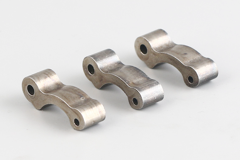
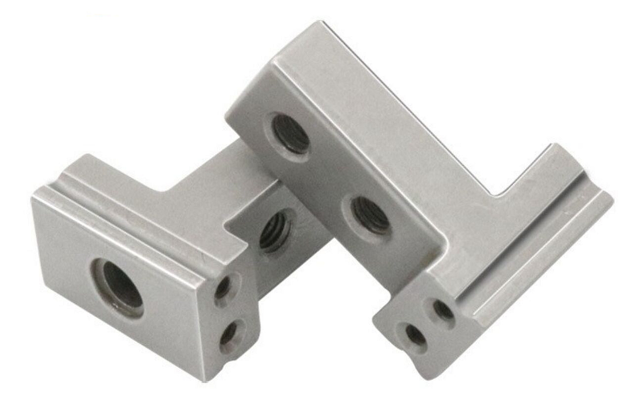
High-volume MIM tooling should be designed around part geometry, feedstock flow, shrinkage compensation, ejection, wear, maintenance, and inspection needs. This FAQ explains how Neway reviews metal injection molding mold design for gears, cams, brackets, latch parts, thin-wall components, medical hardware, and precision metal mechanisms. The practical RFQ problem is to decide whether the MIM tool can repeatedly mold a stable green part that can be debound, sintered, finished, and inspected without costly drift during production.
Why does MIM tooling matter for high-volume production?
MIM tooling controls the green part shape before debinding and sintering. Because the sintered metal part is smaller than the molded green part, the mold must include shrinkage compensation and process-specific design choices. Tooling therefore affects final dimensions, surface condition, filling behavior, ejection, parting lines, gate vestige, and inspection strategy.
In high-volume production, small tooling issues can repeat across many parts. A weak gate location, poor venting, unstable ejection, or poorly placed parting line can create filling defects, distortion, flash, surface marks, or inconsistent datums. Neway reviews tooling together with the full process route rather than treating the mold as an isolated item.
MIM tooling factor | Why it matters | Typical risk | RFQ detail to provide |
|---|---|---|---|
Cavity layout | Controls repeatability and balance across production. | Cavity-to-cavity variation or uneven filling | Annual volume, part size, critical dimensions, appearance areas |
Gate and runner design | Affects feedstock flow, weld lines, gate vestige, and green density. | Short shots, weak areas, difficult gate cleanup | Functional surfaces, no-gate zones, cosmetic surfaces |
Shrinkage compensation | Scales the molded shape toward the final sintered target. | Datum shift, bore error, warpage, profile drift | Material grade, wall thickness, datums, mating parts |
Ejection and parting line | Protects green part geometry and surface quality. | Cracks, deformation, visible marks, flash | Thin walls, ribs, undercuts, visible surfaces, handling constraints |
How should cavity layout, gating, and venting be planned?
Cavity layout should match the expected production volume, part complexity, and inspection needs. Multi-cavity tooling can improve output, but each cavity must fill, pack, eject, and shrink consistently. For small precision MIM parts, cavity balance and repeatability can matter more than simply increasing cavity count.
Gate location should avoid critical datums, sliding surfaces, gear teeth, latch faces, sealing surfaces, and cosmetic areas where gate vestige would create function or appearance problems. Runner design should support stable feedstock flow. Venting should allow trapped gas to escape without creating flash or weak surfaces.
For RFQs, buyers should mark no-gate areas, visible surfaces, machined datums, and critical-to-function features. These drawing notes help Neway plan the tool around final part behavior rather than only mold filling.
How does shrinkage compensation affect mold design?
MIM shrinkage compensation is one of the central tooling decisions. The molded green part is larger than the final sintered part, so the tool must account for expected shrinkage based on material, geometry, wall thickness, sintering support, and secondary operations. Uneven shrinkage can affect bores, flatness, tooth profiles, slots, and mating surfaces.
Neway reviews whether the part is likely to shrink uniformly or whether geometry creates directional shrinkage risk. Long thin sections, uneven wall thickness, unsupported ribs, deep slots, and heavy bosses can require special support or geometry adjustment. Critical dimensions may also need machining allowance after sintering.
The buyer should identify which dimensions must be held as-sintered and which can be finished later. This helps Neway separate tooling compensation from secondary machining strategy.
What mold material, wear, ejection, and maintenance factors matter?
MIM feedstock contains metal powder and binder, so tooling wear and surface condition should be reviewed for production stability. Mold steel selection, surface treatment, polish level, insert design, and maintenance plan affect long-term repeatability. Wear can change cavity dimensions, flash risk, gate condition, and surface appearance.
Ejection must protect the green part. A green MIM part is not the final dense metal part; it can be more sensitive to deformation or cracking. Ejector location, ejection force, draft, undercut strategy, and handling should be reviewed for thin walls, small features, and delicate profiles.
Maintenance planning should include cleaning, inspection of gates and vents, cavity wear checks, ejector condition, and documentation of tool changes. For high-volume programs, tool maintenance is part of the cost and quality plan, not an afterthought.
How should tooling support inspection and process validation?
Tooling should support the measurement plan. If the final part has critical bores, gear teeth, latch surfaces, or flatness requirements, the tool and process should allow stable measurement and repeatable fixturing. Neway may recommend gauges, CMM points, first article inspection, cavity identification, and sampling by cavity when needed.
Process validation should connect the tool to molding, debinding, sintering, heat treatment, machining, finishing, and final inspection. A tool that molds an acceptable green part still needs verification after sintering and secondary operations. Neway reviews first samples, dimensional reports, appearance, surface finish, and function before production release.
Validation item | What it confirms | Tooling implication | Buyer approval output |
|---|---|---|---|
First article inspection | Tooling compensation and critical dimensions | May trigger tool adjustment or process change | Approved sample and dimensional report |
Cavity comparison | Repeatability across cavities | Highlights imbalance or local wear risk | Cavity-specific measurement plan |
Process window review | Molding and sintering stability | Confirms tooling works with feedstock and furnace route | Sampling plan and release criteria |
Maintenance review | Tool condition over repeated production | Prevents drift from wear, blockage, or ejection issues | Maintenance interval and inspection checklist |
What RFQ information helps Neway design high-volume MIM tooling?
A useful tooling RFQ should include 3D models, 2D drawings, annual volume, batch size, material grade, critical dimensions, cosmetic surfaces, no-gate areas, thin walls, undercuts, threads, machining allowance, heat treatment, surface treatment, inspection method, and mating components.
Neway can then review cavity layout, gate location, venting, parting line, shrinkage compensation, ejection, wear management, maintenance planning, and inspection strategy. MIM tooling supports production better when the part design, process route, and quality plan are aligned before tool manufacturing begins.
Related FAQs
Why are custom metal injection molding services suitable for high-volume production?
How does production volume affect the unit cost of metal injection molded parts?
How can custom MIM services maintain part consistency across large production runs?
How are tight-tolerance components controlled during the MIM shrinkage process?
Which design factors affect dimensional accuracy in precision MIM parts?
What tolerances can precision metal injection molding services typically achieve?