How does Neway verify long-term reliability of thermal management solutions?
Long-term reliability for telecom thermal management solutions is verified by linking material selection, manufacturing controls, environmental tests, thermal tests, dimensional inspection, and production validation to the buyer's operating profile. This FAQ explains how ceramic injection molding, aluminum die casting, plastic injection molding, metal injection molding, prototype testing, and process control apply to AAU heat spreaders, ceramic thermal interfaces, RF brackets, housings, covers, and telecommunication cooling assemblies. The practical RFQ problem is to define what evidence proves the thermal solution remains acceptable after temperature cycling, humidity, corrosion, vibration, and assembly stress.
What reliability evidence should buyers request?
Buyers should request evidence that connects environmental exposure to thermal, RF, mechanical, and dimensional performance. A test report is more useful when the report identifies the part condition, test setup, sample quantity, acceptance criteria, and measured change after exposure.
For telecommunication thermal parts, useful evidence may include temperature cycling data, humidity exposure data, corrosion exposure data, thermal resistance measurements, coating inspection, ceramic crack inspection, seal inspection, CMM or fixture inspection, and RF performance checks when the thermal part is also a grounding or shielding feature. The buyer should define final acceptance criteria because Neway's manufacturing validation supports, but does not replace, the buyer's system-level qualification.
Reliability evidence entity | What it checks | RFQ detail required |
|---|---|---|
Temperature cycling data | Thermal expansion, joint stress, cracks, and interface change | Cycle range, dwell time, sample condition, and acceptance criteria |
Humidity or condensation exposure | Seal integrity, corrosion risk, insulation behavior, and contact stability | Humidity condition, powered or unpowered state, and inspection method |
Corrosion or pollution exposure | Coating durability, galvanic risk, and metal interface condition | Exposure chemistry, coating type, and post-test inspection requirement |
Thermal resistance measurement | Heat path performance before and after stress | Heat load, sensor locations, thermal interface material, and airflow condition |
Which environmental tests are relevant for telecom thermal parts?
Relevant environmental tests depend on where the telecom equipment will be installed. Outdoor AAU parts may need temperature cycling, UV exposure, rain or condensation review, corrosion exposure, dust loading, vibration, and thermal-load testing. Indoor baseband or cabinet parts may focus more on heat load, airflow, dust, service access, and material aging.
Neway reviews environmental tests against the specific part function. An aluminum die casting heat sink may need coating and flatness checks after exposure. A CIM ceramic spacer may need crack, dielectric, and dimensional review. A plastic injection molding cover may need heat aging, UV exposure, sealing, and stiffness checks. A metal injection molding RF bracket may need coating, grounding, and dimensional stability checks.
How are CIM material and process controls validated?
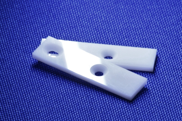
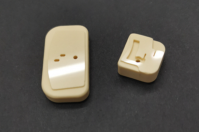
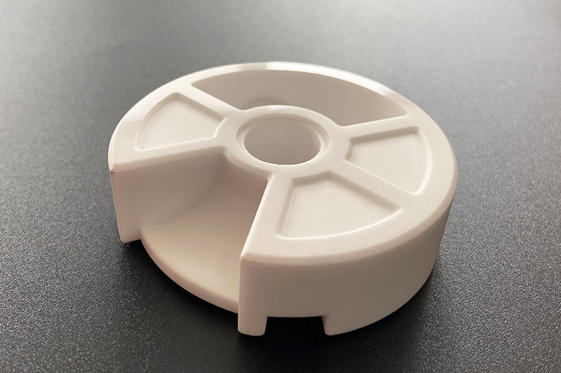
CIM material and process controls are validated by checking ceramic feedstock behavior, molding stability, debinding, sintering, shrinkage, crack risk, dimensional repeatability, and final surface condition. The buyer should specify whether the ceramic part is used for heat transfer, electrical insulation, dielectric control, wear resistance, or mechanical support.
Alumina, zirconia, silicon carbide, and silicon nitride should be validated against different reliability risks. Ceramic selection should be tied to the buyer's thermal, electrical, dimensional, and environmental requirements rather than chosen only by generic material reputation.
How are metal, polymer, and ceramic interfaces checked?
Metal, polymer, and ceramic interfaces should be checked because many thermal failures occur at joints, seals, coatings, and flatness-controlled contact areas. The thermal component may pass material testing but still lose performance if an interface shifts after assembly or environmental exposure.
For a metal heat spreader, Neway may review flatness, machining allowance, coating, and surface roughness. For a polymer cover, Neway may review heat aging, gasket compression, and dimensional stability. For a ceramic interface part, Neway may review contact stress, chipping risk, thermal interface material, and assembly preload. If an interface is also an RF grounding or shielding surface, the buyer should define contact resistance or RF test requirements after environmental stress.
How should prototype and pilot data feed production control?
Prototype and pilot data should be converted into production controls for material lots, process windows, inspection plans, and final acceptance checks. The purpose is to avoid proving reliability only on a hand-built sample that differs from production parts.
Prototyping can identify heat path weaknesses, sealing issues, ceramic stress points, and coating risks. Pilot production should then confirm whether the same thermal and environmental behavior holds after production tooling, finishing, and assembly. If pilot data changes from prototype data, Neway and the buyer should review the material route, tooling, surface treatment, or assembly process before production release.
Validation stage | Evidence to collect | Production control output |
|---|---|---|
Prototype validation | Thermal response, interface behavior, and environmental weak points | Material selection, geometry changes, and test plan updates |
First sample validation | Dimensional report, material condition, coating data, and thermal test data | Tooling correction, finishing plan, and inspection baseline |
Pilot production validation | Sample variation, stress-test results, and assembly repeatability | Process window, sampling plan, and buyer release decision |
Mass production monitoring | Ongoing inspection and agreed functional checks | Lot records, corrective action triggers, and change-control requirements |
What RFQ details help Neway plan reliability validation?
A thermal reliability RFQ should include the part function, installation environment, heat load, target thermal resistance or temperature rise, material preference, assembly stack-up, coating requirement, sealing condition, vibration exposure, environmental test plan, sample quantity, inspection method, and buyer approval criteria. These details allow Neway to build a validation plan around the actual risk of the telecom part.
The buyer should also identify whether the thermal part affects RF shielding, electrical insulation, grounding continuity, or dielectric behavior. That information helps Neway connect CIM, aluminum die casting, plastic injection molding, MIM, and prototype data to the correct reliability checks.
Related FAQs
What environmental factors must be prioritized in 5G AAU thermal design?
How to balance lightweight requirements with thermal efficiency in telecom gear?
How to choose between liquid and air cooling for various telecom applications?
How to select thermal interface material between chip and heatsink?
What tests should be performed on functional prototype parts?
Can aluminum die casting be used for heat dissipation components?
What material and structural solutions enable lightweight high heat dissipation?
What steps take RF components from prototype to full-scale production?