How to select the best thermal interface material between chip and heatsink?
Thermal interface material between a chip and heatsink should be selected by heat load, gap size, surface flatness, contact pressure, electrical isolation, environmental exposure, and assembly process. This FAQ explains how ceramic injection molding, aluminum die casting, CNC prototyping, surface finishing, and reliability testing affect TIM selection for telecom chips, ceramic spacers, heat spreaders, cold plates, RF modules, and heatsink assemblies. The practical RFQ problem is to define the interface condition clearly enough for Neway to review whether a thermal pad, grease, phase-change material, gap filler, or ceramic interface part fits the manufacturing and validation plan.
What should buyers define before selecting a TIM?
Buyers should define the heat load, chip size, heatsink material, interface area, gap tolerance, allowable compression, electrical isolation requirement, assembly pressure, rework requirement, and environmental exposure. TIM selection cannot be separated from the mechanical stack-up.
In telecommunication hardware, the TIM may sit between a chip and an aluminum heatsink, a ceramic spacer and metal housing, a power device and cold plate, or an RF module and heat spreader. Each interface has different flatness, pressure, vibration, and insulation requirements. The RFQ should state whether the TIM must transfer heat only, electrically isolate the chip, absorb assembly tolerance, or maintain contact after temperature cycling.
TIM selection entity | Buyer question | Manufacturing implication |
|---|---|---|
Gap size and tolerance | How much variation exists between chip and heatsink? | Gap filler or compliant pad may be reviewed instead of a thin grease layer |
Surface flatness | How flat are the ceramic, metal, or cast surfaces? | CNC finishing, inspection, or surface control may be needed |
Contact pressure | How much compression can the chip and assembly tolerate? | Fastener pattern, preload, and TIM thickness must be reviewed together |
Electrical isolation | Must the interface isolate voltage or RF paths? | Ceramic spacer, insulating TIM, or controlled coating may be required |
How do common TIM types differ for telecom hardware?
Common TIM types differ by thickness control, compression behavior, reworkability, pump-out risk, electrical insulation, and sensitivity to surface finish. The buyer should choose the TIM type after reviewing the actual chip-to-heatsink stack-up, not only a thermal conductivity value.
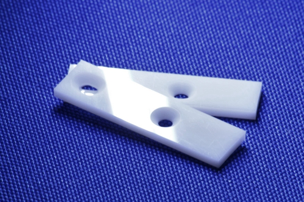
Thermal grease may fit controlled flat interfaces with stable assembly pressure, but grease needs process control during dispensing. Thermal pads may fit serviceable modules and moderate gaps, but pad compression must be controlled. Gap fillers may fit uneven assemblies, but dispensing and cure behavior matter. Phase-change materials may fit repeated thermal cycling when the buyer validates the phase-change behavior in the final assembly. Ceramic interface parts may be reviewed when a hard insulating or dielectric component is required in the heat path.
How do chip, ceramic, and heatsink surfaces affect TIM selection?
Surface flatness, roughness, cleanliness, coating, and material hardness affect TIM thickness and contact quality. A TIM cannot fully compensate for a warped heatsink base, a chipped ceramic edge, or an uncontrolled coating buildup.
Aluminum die casting heatsinks may need machined interface pads, coating control, or flatness inspection before TIM selection. CNC machining prototyping can help evaluate interface flatness and pressure distribution before production tooling. Surface finishing should be reviewed carefully because some finishes protect the part while others can change contact resistance, surface roughness, or coating thickness at the TIM interface.
How do CIM materials change the thermal interface design?
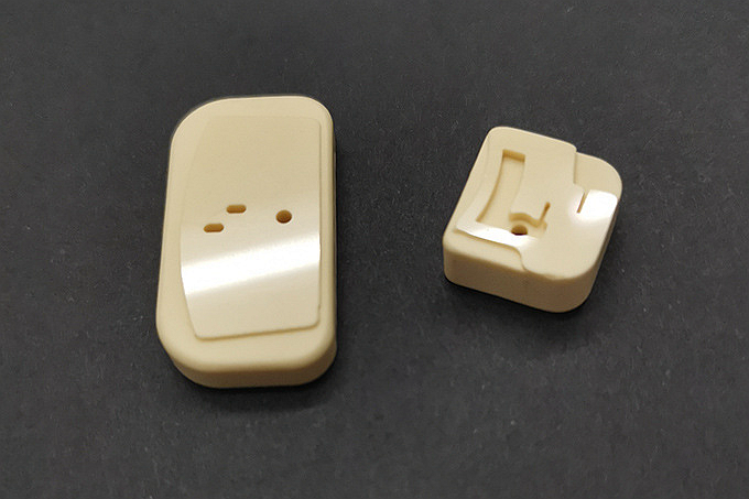
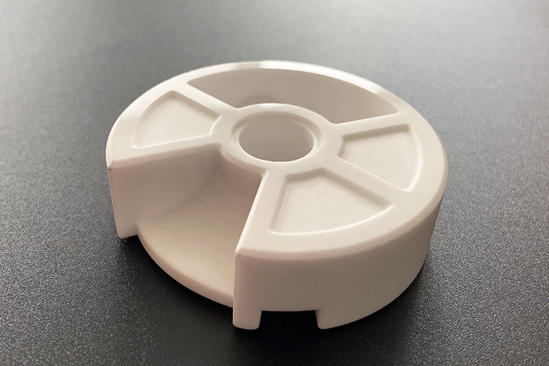
CIM materials change the thermal interface design when the interface needs dielectric behavior, wear resistance, stiffness, dimensional stability, or a ceramic surface in the heat path. A ceramic component can be part of the interface stack, but the buyer must define whether the ceramic part is an insulator, spacer, heat-related support, RF component, or structural feature.
Alumina, zirconia, silicon carbide, and silicon nitride should be compared against the electrical, mechanical, thermal, and environmental requirement. The TIM must also be compatible with ceramic surface finish, assembly pressure, edge condition, and temperature cycling.
What reliability tests validate a TIM choice?
TIM validation should measure thermal resistance before and after environmental stress, assembly compression, vibration, and rework if rework is part of the service plan. The test should use representative chip surfaces, heatsink surfaces, fastener preload, and final part finishes.
Useful validation may include thermal cycling, humidity exposure, vibration, pressure mapping, thermal resistance measurement, visual inspection for migration or voids, and electrical isolation checks when needed. Prototyping allows buyers to compare TIM types before committing to a production heatsink, ceramic spacer, or enclosure design.
Validation item | What it checks | RFQ input needed |
|---|---|---|
Thermal resistance test | Heat transfer through the final stack-up | Heat load, sensor location, airflow condition, and acceptance limit |
Compression or pressure check | TIM contact across the chip and heatsink surface | Fastener pattern, preload, gap tolerance, and TIM thickness |
Environmental stress test | Change after temperature, humidity, vibration, or aging exposure | Exposure profile, sample condition, and inspection method |
Electrical isolation test | Insulation between chip, ceramic, and heatsink where required | Voltage requirement, dielectric path, and surface condition |
What RFQ details help Neway review a TIM stack?
A TIM RFQ should include chip size, heat load, heatsink material, ceramic or metal interface parts, target thermal resistance, surface flatness, roughness, coating, gap tolerance, contact pressure, electrical isolation requirement, environmental exposure, rework requirement, and validation test method. These details allow Neway to review the TIM together with CIM, aluminum die casting, CNC prototyping, surface finishing, and production inspection.
The buyer should also identify which dimensions are measured after machining, after coating, and after assembly. That distinction helps prevent a TIM from being selected for a theoretical gap that does not match the final manufactured part.
Related FAQs
How does Neway verify long-term reliability of thermal management solutions?
How to choose between liquid and air cooling for various telecom applications?
How to balance lightweight requirements with thermal efficiency in telecom gear?
What environmental factors must be prioritized in 5G AAU thermal design?
Can aluminum die casting be used for heat dissipation components?
What factors most impact natural convection efficiency in heatsink design?
What tests should be performed on functional prototype parts?
How to balance conductivity, heat, weight, and cost when selecting RF materials?