How to simulate real EV operating conditions during prototype validation?
This FAQ explains how EV operating conditions can be simulated during prototype validation for drivetrain housings, motor supports, shafts, brackets, covers, cooling structures, and small drivetrain mechanisms. The manufacturing route may include prototyping, CNC machining prototyping, 3D printing prototyping, aluminum die casting, precision casting, metal injection molding, plastic injection molding, or sheet metal fabrication. The practical RFQ problem is to convert EV drive cycle, torque-speed profile, thermal exposure, vibration load, environmental exposure, inspection evidence, and buyer validation criteria into a clear prototype test plan.
What EV operating conditions should be simulated during prototype validation?
EV prototype validation should simulate the conditions that control the part's real function. For drivetrain prototypes, the most common conditions are torque transfer, rotational speed, bearing alignment, vibration, thermal cycling, coolant exposure, sealing pressure, corrosion exposure, and assembly loads.
A motor housing, inverter enclosure, gear carrier, cooling plate, shaft support, latch mechanism, and bracket each sees a different part of the EV duty cycle. A housing may need thermal and sealing review. A shaft or gear carrier may need runout, torque, and vibration review. A plastic cover may need heat aging, impact, clip retention, and sealing review. A MIM lock or small mechanism may need wear, pin fit, hardness, and functional cycling review.
The RFQ implication is that buyers should define the component-level test conditions instead of asking for a general EV validation. Neway can support prototype manufacturing and inspection planning, while the final system approval should follow the buyer's EV validation program.
How are EV drive cycles translated into component-level prototype tests?
Drive cycles must be converted into loads that a prototype supplier can build and inspect against. Buyer engineering teams may provide torque-speed profiles, regenerative braking events, acceleration cycles, start-stop sequences, temperature profiles, coolant conditions, and vibration spectra. These inputs become the test matrix for specific drivetrain components.
For example, an e-axle housing RFQ may convert the drive cycle into torque reaction loads, bearing seat alignment requirements, thermal expansion checks, coolant pressure checks, and sealing tests. A shaft or gear carrier RFQ may convert the drive cycle into runout limits, hardness requirements, backlash checks, and torque cycling. A cover or cable carrier RFQ may convert the operating condition into clip retention, vibration, heat aging, sealing, and chemical exposure checks.
The RFQ implication is that the test plan should connect every test to a component risk. A long list of tests is not useful unless the supplier knows the acceptance criteria, sample quantity, test fixture status, and reporting format.
Which prototype route best represents EV production conditions?
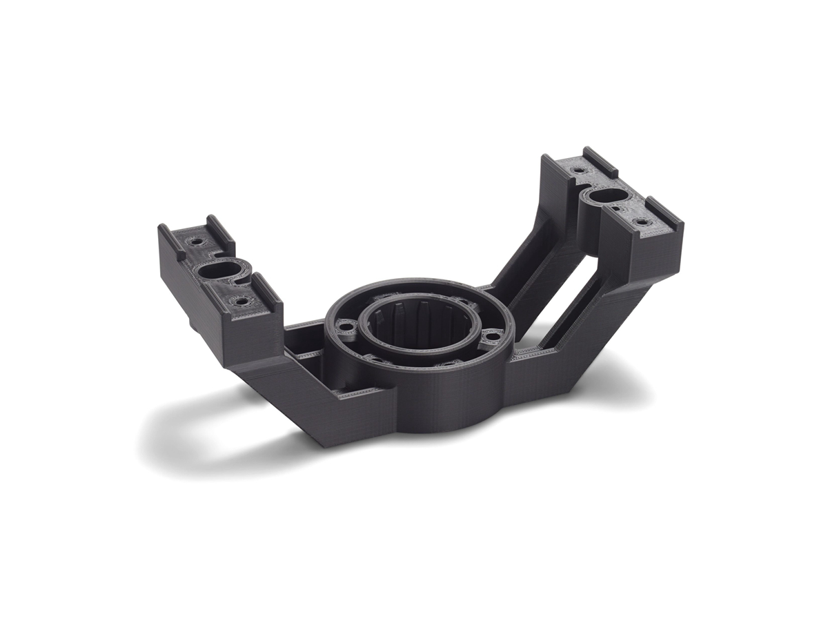
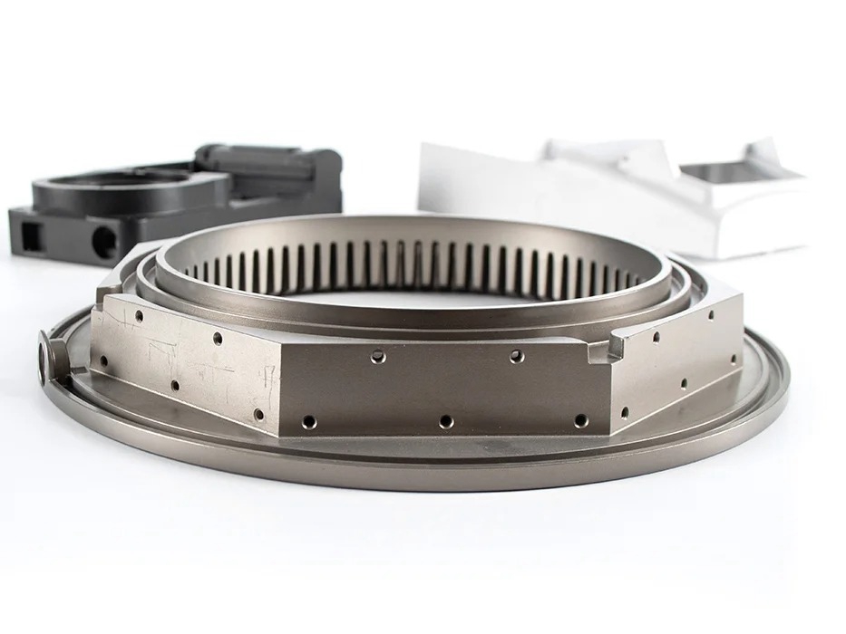
The prototype route should represent the decision being tested. CNC machining can create accurate datums, bearing seats, bolt patterns, and sealing faces for functional assembly checks. 3D printing can help evaluate package space, airflow, cable routing, bracket clearance, and test fixture fit before metal or molded samples are produced.
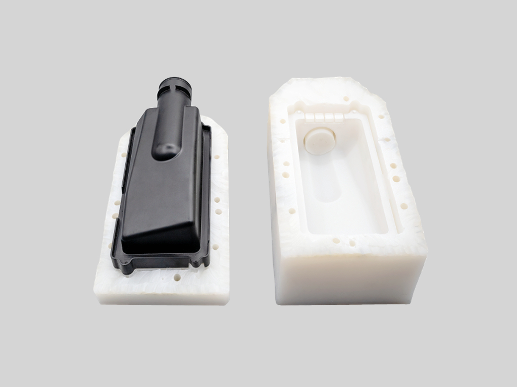
When the buyer needs production-intent material behavior, the prototype route may need to move closer to the planned process. Aluminum die casting or precision casting may be needed when cast wall thickness, ribs, porosity risk, cooling channels, or thermal expansion behavior matter. Metal injection molding may be needed for small drivetrain mechanisms where sintering shrinkage, density, and secondary machining affect function. Plastic injection molding may be needed when molded resin behavior, inserts, screw bosses, clips, and fiber orientation are part of the validation risk.
The RFQ implication is that an early prototype may be fast but not fully representative. Buyers should state whether the sample is for geometry, assembly, thermal behavior, torque loading, sealing, durability screening, or production-process comparison.
How should mechanical, thermal, vibration, and environmental tests be combined?
EV operating conditions are coupled. A drivetrain component may pass a room-temperature fit check but fail after heat cycling, coolant exposure, vibration, or torque loading. Prototype validation should therefore combine tests in a sequence that reflects the part risk.
EV condition | Prototype part affected | Manufacturing route to consider | Validation evidence to request |
|---|---|---|---|
Torque and speed cycle | Shaft, gear carrier, bearing support, motor mount | CNC machining, precision casting, aluminum die casting, MIM for small mechanisms | Runout data, hardness check, dimensional inspection, torque test record, wear review |
Thermal cycling and heat soak | Motor housing, inverter enclosure, cooling plate, plastic cover | Aluminum casting, CNC machining, plastic injection molding, 3D printing for early fit checks | Temperature profile, thermal expansion review, leak test, material condition, inspection report |
Vibration and shock | Bracket, housing, cover, cable carrier, latch mechanism | Sheet metal fabrication, casting, plastic molding, MIM, CNC machining | Fixture setup, vibration profile, fastener check, crack inspection, functional test after vibration |
Corrosion, humidity, coolant, and road contamination | Underbody bracket, housing, cover, cooling channel, fastener interface | Metal prototype with surface finishing, molded plastic, coated casting, fabricated bracket | Coating thickness, masking plan, leak result, corrosion exposure method, visual and dimensional report |
Assembly and service load | Threaded boss, insert, clip, sealing flange, connector mount | CNC machining, casting with secondary machining, insert molding, plastic injection molding | Torque check, insert pull-out, gasket compression, thread inspection, assembly trial record |
How do material condition and surface finishing affect EV prototype tests?
Material condition and surface finishing can change prototype results. A metal part that will be heat treated in production should not be tested in an untreated condition unless the buyer clearly accepts the limitation. Heat treatment may affect hardness, strength, distortion, and machining sequence.
Surface finishing also affects EV prototype validation. Aluminum parts may require anodizing, conversion coating, paint, or anodized aluminum review. Metal brackets, housings, and covers may use powder coating or other surface finishing routes. The finish plan should identify sealing surfaces, threaded holes, electrical contact areas, masked areas, coating thickness, and corrosion exposure.
The RFQ implication is that test samples should match the intended material condition wherever the test result depends on hardness, corrosion resistance, sealing, friction, or electrical contact.
What RFQ details help Neway support EV prototype validation?
Provide the prototype part list, 3D models, 2D drawings, material candidates, planned production process, test purpose, sample quantity, load cases, torque-speed profile, temperature range, vibration profile, coolant or chemical exposure, sealing requirement, surface finishing requirement, inspection method, and reporting format. Also state which tests are required before design release and which tests are for later system validation.
Neway can then review whether CNC machining, 3D printing, casting, MIM, plastic injection molding, or sheet metal fabrication can support the prototype objective. The review can also identify secondary machining, heat treatment, coating, inserts, fixtures, and dimensional reports needed before the sample enters testing.
The practical answer is that realistic EV prototype validation starts with a buyer-defined test matrix and production-aware samples. The closer the RFQ connects EV operating conditions to component-level risks, the more useful the prototype results will be for the next design decision.
Related FAQs
What is the shortest lead time to a fully tested drivetrain prototype?
What tests should be performed on functional prototype parts?
What information should buyers provide for an accurate prototype quote?
What are the main differences between 3D printing and CNC machining for automotive prototypes?
What is the development cycle for motor components from prototype to production?
What is the typical development cycle for battery components from prototype to production?