Rapid Prototyping and Aerospace Component Verification
Aerospace Rapid Prototyping Verification RFQ Decision: This article explains how buyers can use CNC machining prototyping, 3D printing prototyping, and rapid molding prototyping to verify aerospace component form, fit, function, material behavior, and inspection requirements before production release. The practical RFQ problem is defining prototype purpose, material simulation limits, test method, dimensional inspection, surface finish, heat treatment, and buyer approval criteria without treating a prototype as final aerospace qualification.
What Prototype Decision Should Buyers Make First?
Buyers should first decide what the aerospace prototype must prove. A prototype may verify shape, assembly fit, connector location, airflow path, bracket stiffness, thermal exposure, surface finish, packaging space, or a manufacturing concept.
The engineering reason is that prototype route selection depends on the validation question. A visual model, fit-check sample, functional prototype, thermal test piece, and pre-production sample can require different materials, processes, inspection reports, and test plans.
For quotation, the buyer should provide drawings, CAD files, target prototype quantity, intended test, required material, critical surfaces, tolerance needs, finishing requirement, and whether the sample is used for design learning or buyer approval.
Which Prototype Route Fits Aerospace Component Verification?
The prototype route should be selected from geometry, material, time, test requirement, and how closely the sample must represent production. Buyers should not choose a route only by speed.
Prototype Route | Best-Fit Verification Need | RFQ Detail Buyers Should Provide |
|---|---|---|
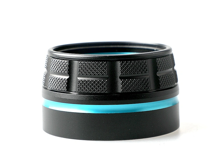
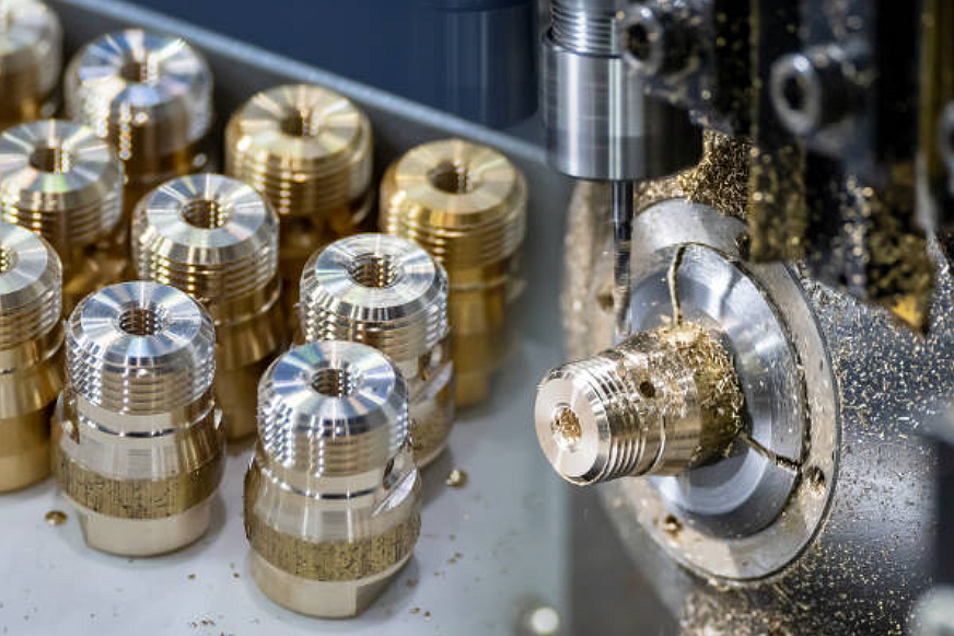
CNC machining prototyping | Metal or plastic parts needing accurate datums, machined surfaces, threaded features, and functional fit | Material grade, tolerances, datum scheme, surface finish, and inspection report. |
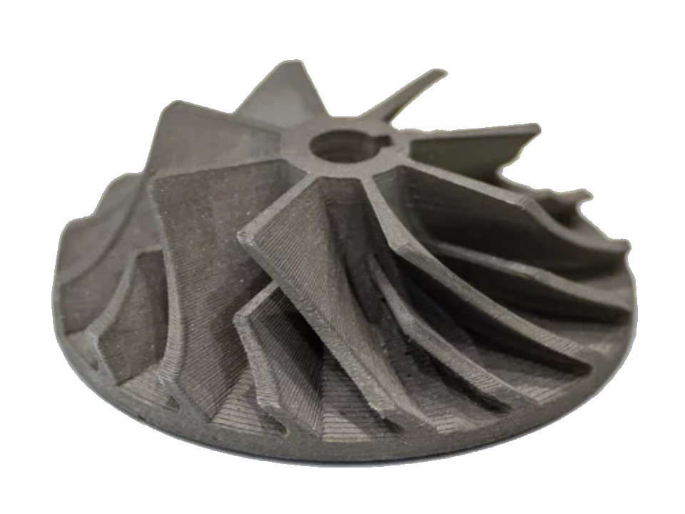
3D printing prototyping | Complex geometry, ducting, lightweight concepts, quick iteration, and early assembly checks | Prototype purpose, material limits, surface finish, post-processing, and test boundary. |
Plastic samples needing molded geometry, resin behavior, snap features, or pilot-lot evaluation | Resin choice, tool life expectation, gate location, cosmetic surfaces, and sample quantity. | |
Hybrid prototype route | Assemblies combining machined metal, printed features, molded covers, or secondary finishing | Assembly drawing, joining method, part interfaces, and inspection responsibility. |
The buyer should state whether the prototype must be production-intent or only representative for a specific test.
How Should Materials And Heat Treatment Be Defined?
Material should be specified according to the test purpose. If the prototype is used for fit only, a substitute material may be acceptable. If the prototype is used for load, thermal, wear, or fatigue review, the buyer should define the actual material grade or explain the acceptable simulation.
For metal prototypes, buyers should define alloy grade, heat treatment, surface condition, and any material certificate requirement. For polymer prototypes, buyers should define resin, reinforcement, flame or thermal requirement if needed, and surface finish. For 3D printed prototypes, buyers should define whether printed material properties are acceptable for the test.
Material assumptions should be visible in the report. A prototype that passes a fit check does not automatically validate production material performance.
What Verification Tests Should Be Planned?
Verification tests should match the prototype purpose. Buyers may need dimensional inspection, assembly fit checks, thermal exposure review, vibration or load testing, surface finish review, leak testing, connector checks, or post-test inspection.
Verification Entity | Relevant Method | Buyer Decision Supported |
|---|---|---|
Dimensional fit | CMM dimensional inspection, gauges, or fixture checks | Confirm assembly datums, hole locations, and interface surfaces. |
Surface shape | Compare prototype surface geometry to CAD or a revised design. | |
Internal features | Review hidden channels, voids, or internal geometry when required. | |
Structural behavior | Support buyer validation under defined loads, fixtures, and stop criteria. |
The RFQ should state who owns the test plan and who approves the result. Supplier inspection can support the buyer's decision, but the buyer's engineering process should define the acceptance rule.
How Should Prototype Feedback Support Production Planning?
Prototype feedback should be converted into design changes, process choices, and production risks. A successful prototype may show that the geometry works, but it may still need production route review for tooling, material, tolerance, cost, and inspection evidence.
For CNC prototypes, production may move to casting, molding, MIM, or another route. For 3D printed prototypes, production may require redesign for machining, molding, or casting. For rapid molded prototypes, production tooling may need different cooling, cavity count, automation, and validation planning.
The buyer should identify which prototype features are frozen and which can change before production. This prevents prototype lessons from being lost during transition.
Buyers should also document prototype limitations in the RFQ record. A substitute material, printed surface, simplified heat treatment, or temporary fixture may be acceptable for early learning, but the limitation should be visible before the team uses the result for tooling, qualification planning, or supplier comparison.
What Should Buyers Include In An Aerospace Prototype RFQ?
A complete RFQ should include the drawing, CAD model, revision level, prototype purpose, material requirement, quantity, critical features, required inspection, finish requirement, heat treatment, test plan, report format, and approval responsibility.
The buyer should also state whether the prototype is for concept review, fit check, functional testing, process comparison, customer demonstration, or pre-production approval. Each purpose changes the required manufacturing evidence.
This structure helps the supplier quote aerospace rapid prototyping accurately and helps the buyer use prototype evidence for the right decision before production release.
Related FAQs