What is the development cycle for motor components from prototype to production?
The motor component development cycle moves from RFQ review to prototype builds, functional testing, DFM review, tooling, pilot production, and controlled mass production for rotors, shafts, soft magnetic parts, housings, connector inserts, and overmolded assemblies. The manufacturing route may include prototyping, CNC machining, 3D printing, MIM, aluminum die casting, insert molding, overmolding, dynamic balancing, and production inspection. The practical RFQ problem is to define prototype purpose, motor speed range, magnetic path, thermal load, CTQ dimensions, and validation records before Neway selects the process path from prototype to production.
What stages define a motor component development cycle?
A motor component development cycle should be staged so that each step answers a specific manufacturing and validation question. The cycle normally begins with RFQ clarification, then moves through prototype selection, functional testing, DFM review, tooling or fixture development, pilot build, quality approval, and production launch.
The reason is that motor components combine rotating, magnetic, thermal, electrical, and assembly requirements. A rotor needs runout and balance control. A soft magnetic part needs magnetic property control. A motor housing needs heat path and mounting control. An overmolded connector needs insulation, retention, and sealing control.
Development stage | Motor component question | Manufacturing process focus | Buyer decision before moving forward |
|---|---|---|---|
RFQ review | What function must the motor component prove? | Requirement review, material comparison, process comparison | Define CTQ features, duty cycle, speed range, and validation scope |
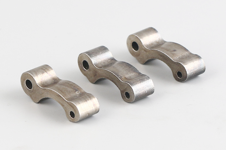
Prototype build | Does the geometry fit the motor assembly? | CNC machining, 3D printing, MIM samples, or die cast prototypes | Approve prototype purpose, material route, and inspection method |
Functional testing | Does the part support rotation, heat, magnetic, or insulation requirements? | Dynamic balance, runout checks, thermal review, magnetic checks, pull-out checks | Freeze design changes needed before tooling |
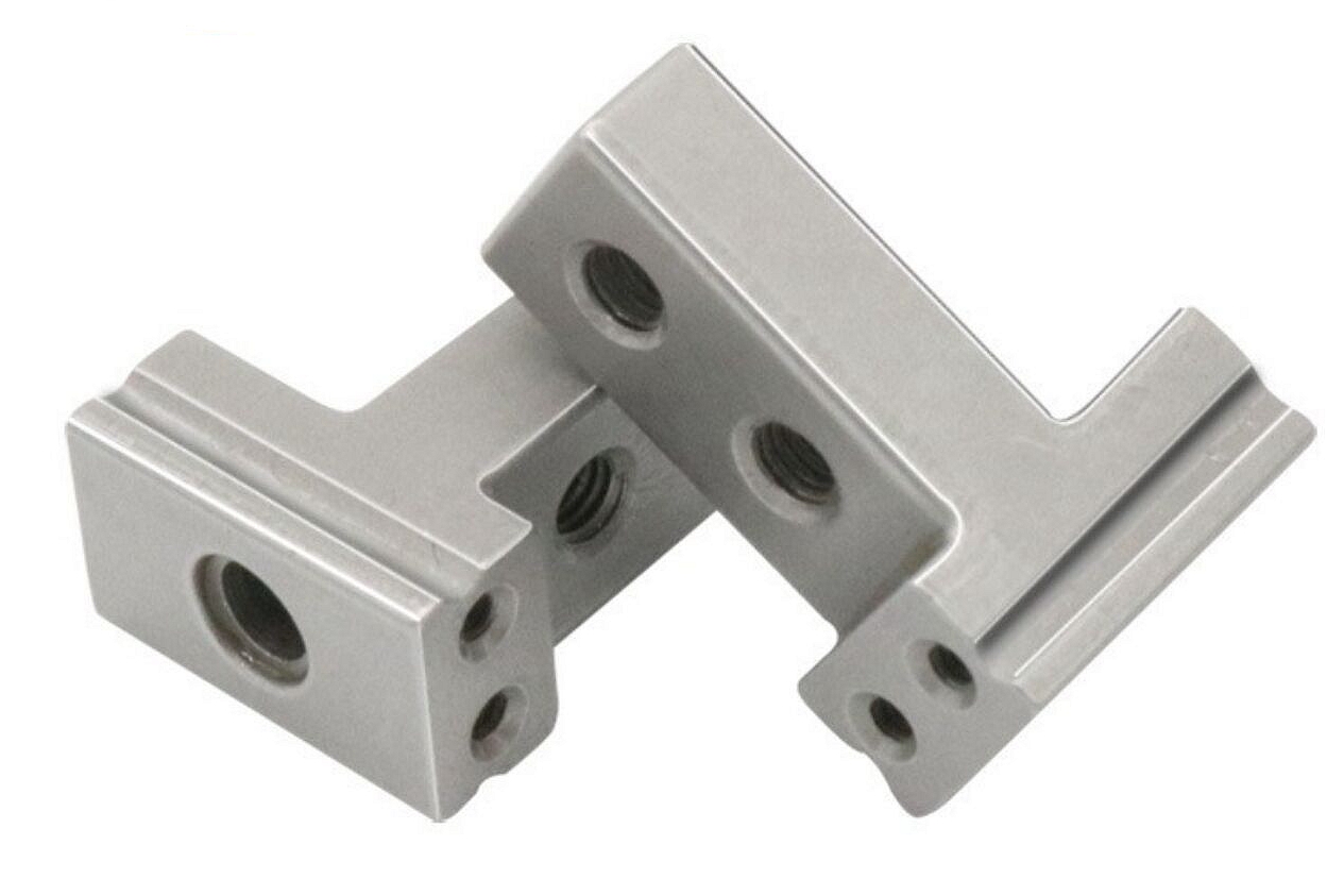
DFM and tooling | Can the design repeat in production? | MIM tooling, casting tooling, machining fixtures, molding tools, gauges | Approve production drawing, datum scheme, and control plan |
Pilot and production launch | Can production records support repeatable quality? | First-article inspection, process window, traceability, final inspection | Approve production release evidence and shipment documentation |
What RFQ inputs are needed before prototype selection?
Before prototype selection, buyers should provide the 3D model, 2D drawing, motor component function, material candidates, operating temperature, speed range if rotating, magnetic requirement, thermal interface, insulation requirement, assembly stack-up, expected production volume, and required reports.
For rotors and shafts, the RFQ should identify the rotation axis, bearing seats, runout tolerance, balance target, magnet pocket geometry, and assembly state. For soft magnetic parts, the RFQ should define permeability, coercivity, core loss, frequency, heat treatment, and magnetic test method. For housings and brackets, the RFQ should define thermal pads, mounting faces, sealing surfaces, coating zones, and machined datums.
The buyer decision is prototype purpose. A visual prototype can check envelope and assembly space, but a functional motor component prototype needs material, datum, surface, and test conditions that resemble the intended production route.
Which prototype route fits rotors, housings, and magnetic components?
Prototype route should match the risk being tested. CNC machining prototyping is useful for shaft bores, bearing seats, rotor datums, flat thermal pads, and tight metal interfaces. 3D printing prototyping is useful for early packaging, airflow, cover geometry, and assembly clearance checks.
Metal injection molding should be reviewed when the motor component is a small complex metal part, soft magnetic part, compact rotor feature, or high-volume component with geometry that is difficult to machine from solid stock. Aluminum die casting may fit motor housings, heat-dissipation covers, and structural frames. Insert molding and overmolding may fit connector interfaces, insulated terminals, seals, strain relief, and motor-related plastic-metal assemblies.
The RFQ implication is that one prototype may not answer every question. A machined aluminum rotor sample can check geometry and runout, but the same sample may not prove MIM shrinkage, sintered density, or magnetic behavior.
What functional tests should be planned before DFM freeze?
Functional tests should be planned around the motor component's real risk. Rotating parts may need runout measurement, concentricity checks, dynamic balance review, assembly fit, and vibration feedback. Soft magnetic parts may need magnetic property testing under the buyer's defined test method. Thermal housings may need flatness checks, thermal interface review, and surface treatment review.
Connector and overmolded parts may need insert position checks, pull-out testing, dielectric spacing review, sealing checks, and thermal cycling review if the buyer requires it. Structural motor parts may need load path review, thread checks, coating checks, and dimensional inspection.
Neway can support prototype manufacturing and part-level inspection, but final motor assembly validation belongs to the buyer's system test plan. The RFQ should separate supplier part evidence from buyer motor-system evidence before DFM freeze.
How does DFM prepare MIM, machining, casting, and overmolding for production?
DFM prepares motor components for production by translating prototype feedback into manufacturable geometry, tooling features, inspection datums, and process controls. For MIM, DFM should review feedstock, gate location, wall thickness, sintering shrinkage, distortion risk, density requirement, and secondary machining allowance.
For CNC-machined motor features, DFM should review datum sequence, fixture access, tool reach, burr control, and inspection frequency. For die cast housings, DFM should review wall thickness, ribs, bosses, porosity-sensitive areas, machined pads, and surface finishing zones. For insert molding and overmolding, DFM should review insert position, resin flow, bonding surface, shrinkage, insulation spacing, and pull-out requirements.
The buyer should approve the production drawing only after DFM findings are reflected in tolerances, datums, notes, and inspection requirements. A design that works as a prototype can still create production risk if shrinkage, fixture access, or assembly stack-up is not reviewed before tooling.
What happens during tooling, bridge builds, and pilot production?
Tooling, bridge builds, and pilot production shift the program from design exploration to production evidence. Tooling may include MIM molds, die casting tools, machining fixtures, gauges, insert molding tools, and assembly fixtures. Bridge builds may use temporary fixtures or limited tooling to confirm process direction before full production release.
Pilot production should confirm that the process can repeat the required features. The pilot build may include first-article inspection, cavity comparison, shrinkage review, runout checks, dynamic balance reports, magnetic property checks, insert pull-out checks, coating review, and packaging review.
If the buyer requires FAI, PPAP, control plans, special characteristics, or specific report formats, those requirements should be agreed before pilot production. Documentation created after the pilot run may not capture the process evidence the buyer expects.
How does quality control carry into motor component mass production?
Quality control carries into mass production by keeping the approved material, tooling, process window, inspection method, and traceability records aligned with the pilot build. The same CTQ features approved during pilot production should remain visible in the production control plan.
Neway's quality assurance planning may include incoming material checks, in-process inspection, final inspection, lot records, and shipment reports. For motor components, production records may include alloy lot, resin lot, heat treatment batch, coating batch, machining setup, mold cavity, dynamic balance data, magnetic test data, and dimensional reports.
The buyer should specify whether the project needs lot-level traceability or part-level traceability. The production launch should not be approved until the buyer and Neway agree on which reports are required with each shipment.
What buyer decisions can delay motor component launch?
Motor component launches are commonly delayed by late changes to material, bearing datum, balance target, magnetic test method, heat treatment, coating mask, insert specification, insulation spacing, thermal pad flatness, or documentation format. These changes affect tooling, inspection, and production controls.
Buyers can reduce delay by approving the prototype route, functional test plan, DFM changes, tooling release drawing, pilot acceptance criteria, and production documentation in sequence. The clearest development cycles state what evidence is needed before each stage moves forward.
Related FAQs
How do Neway motor components meet automotive safety and reliability?
How to control rotor dynamic balance to meet NVH requirements?
How to protect soft magnetic properties during manufacturing?
What material and structural solutions enable lightweight, high heat dissipation?
How should rotating parts for brushless motors be designed for stability and life?
What tooling considerations are important for high-volume MIM production?
How does Neway ensure quality consistency in mass-produced precision components?
What quality inspection methods are used for tight tolerance MIM components?