How should rotating parts for brushless motors be designed for stability and life?
Rotating parts for brushless motors should be designed for stability and life by controlling material, mass distribution, shaft and hub geometry, magnet retention, bearing seats, dynamic balance, heat treatment, surface condition, and validation testing. This FAQ explains how Neway reviews metal injection molding, aluminum die casting, plastic injection molding, magnetic alloys, machining, and inspection for motor shafts, rotor hubs, magnet carriers, fan impellers, spacers, and compact rotating assemblies. The practical RFQ problem is to define the speed range, load case, balance requirement, material route, and life test before the buyer approves the rotating part design.
Which rotating part functions should buyers define first?
Buyers should define whether the part transmits torque, holds magnets, supports bearings, moves air, controls inertia, or locates the rotor stack. Each function changes the material, tolerance, surface, and validation requirement.
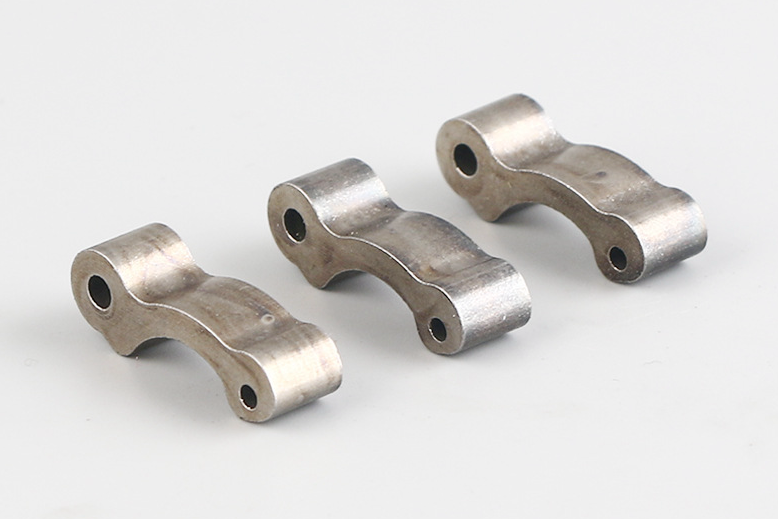
Brushless motor assemblies may include a shaft, rotor hub, magnet carrier, sleeve, fan, retaining ring, spacer, and bearing support. Metal injection molding may be reviewed for compact metal rotor features, hubs, sleeves, and small high-strength parts when geometry and volume support tooling. Aluminum die casting may be reviewed for lightweight hubs or housings, while plastic injection molding may support fan impellers, insulation features, or covers. The RFQ should separate rotating mass features from non-rotating housing features.
Rotating part entity | Stability or life risk | RFQ input needed |
|---|---|---|
Shaft and bearing seat | Runout, vibration, wear, and bearing load variation | Datum scheme, bearing fit, surface finish, and hardness target |
Rotor hub or sleeve | Imbalance, cracking, and magnet position shift | Speed range, material grade, wall thickness, and balance target |
Magnet carrier | Magnet movement, adhesive failure, and radial growth | Magnet size, retention method, temperature, and assembly process |
Fan or impeller | Airflow loss, noise, blade damage, and mass imbalance | Blade geometry, material, speed range, and balance method |
Which material routes support brushless motor rotating parts?
The material route should match torque, speed, magnetic behavior, weight, fatigue, temperature, corrosion exposure, and production volume. A rotating part should not be selected by density alone because imbalance, heat, wear, and retention loads can control the design.
MIM material pages such as MIM 17-4 PH, MIM 4140, MIM 4340, MIM 420, and MIM Fe-50Co can support early material review depending on strength, corrosion, heat treatment, or magnetic requirements. Buyers may also review aluminum die casting for lightweight rotor-adjacent structures and plastic injection molding for fan or insulation features.
How do geometry, tolerance, and balance control stability?
Geometry, tolerance, and balance control whether the rotor runs smoothly at the specified speed. Small errors in concentricity, wall thickness, magnet position, or fan blade mass can create vibration, noise, bearing load, and reduced life.
The drawing should identify balance datums, bearing datums, concentricity requirements, runout limits, wall thickness symmetry, magnet pocket positions, and any post-sintering or post-machining surfaces. MIM shrinkage control, machining allowance, and inspection method must be planned before tooling. If the buyer has a noise, vibration, and harshness target, the RFQ should state how the rotor will be balanced and how the balance result will be measured.
Design control | Motor stability issue | Manufacturing or inspection control |
|---|---|---|
Concentricity and runout | Vibration, bearing wear, and rotor-stator clearance risk | Datum design, machining plan, and CMM inspection |
Mass distribution | Dynamic imbalance and acoustic noise | Wall symmetry, magnet pocket control, and balance test |
Magnet pocket geometry | Magnet shift, uneven magnetic force, and assembly variation | Tooling tolerance, adhesive gap, and retention inspection |
Fan blade geometry | Airflow variation, blade stress, and imbalance | Mold flow, material selection, and visual inspection |
How should magnet retention and assembly be designed?
Magnet retention should be designed for centrifugal load, adhesive behavior, thermal expansion, assembly tolerance, and service environment. A brushless motor rotor can fail if the magnet carrier design does not control pocket geometry, bonding area, and radial restraint.
Retention options may include adhesive, mechanical pockets, sleeves, retaining rings, overmolded features, or hybrid designs depending on the motor speed and environment. The RFQ should state magnet material, magnet size, adhesive or retention plan, operating temperature, balance method, and whether the rotor will be tested after thermal cycling or vibration. Neway reviews the rotating part as an assembly rather than as an isolated metal component.
How do heat treatment, surface condition, and inspection support life?
Heat treatment and surface condition support life by controlling hardness, wear, fatigue response, corrosion behavior, and dimensional stability. These requirements should be tied to the shaft, hub, bearing seat, magnet carrier, or fan feature that needs protection.
Heat treatment may be reviewed for shafts, hubs, sleeves, and high-load MIM components. Inspection may include CMM measurement, runout measurement, hardness, surface roughness, density, microstructure, dynamic balance, fatigue testing, and functional motor testing. Buyers can review related methods such as CMM dimensional inspection and fatigue testing for structural validation when defining the validation plan.
What RFQ details help Neway design rotating parts for stability and life?
An RFQ should include 3D CAD, 2D drawing, speed range, torque profile, duty cycle, rotor mass target, balance requirement, concentricity requirement, runout requirement, material preference, magnetic requirement, magnet retention method, bearing fit, heat treatment, surface finish, secondary machining, sample quantity, production volume, and validation method. These details let Neway review rotating part stability through material, MIM tooling, shrinkage control, machining, assembly, balance, and testing.
The buyer should also identify the main risk: imbalance, bearing wear, magnet shift, fatigue cracking, corrosion, heat distortion, noise, or cost. That priority helps Neway choose the manufacturing and validation controls that matter for the motor application.
Related FAQs
How to control rotor dynamic balance to meet NVH requirements?
How do Neway motor components meet automotive safety and reliability requirements?
What is the development cycle for motor components from prototype to production?
How to protect soft magnetic properties during manufacturing?
How does Neway control quality consistency in mass-produced precision components?
What quality inspection methods are used for tight-tolerance MIM components?
What tolerances can precision metal injection molding services typically achieve?
Which materials are suitable for metal injection molding MIM?