What common issues arise in plasma cutting operations?
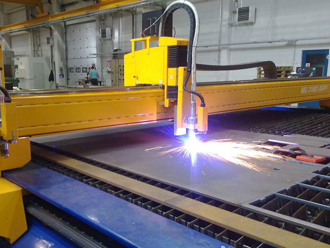
Common plasma cutting issues include dross, rough edges, bevel or taper, oversized holes, arc instability, torch-height variation, consumable wear, heat distortion, and inconsistent cut quality between material batches. For buyers quoting brackets, frames, guards, panels, base plates, and weldment blanks, the practical RFQ problem is whether the plasma cutting route can control these defects before bending, welding, coating, machining, and inspection.
Which defects most often affect plasma-cut parts?
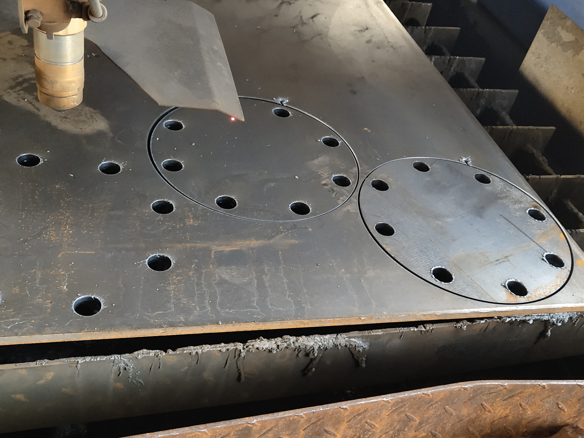
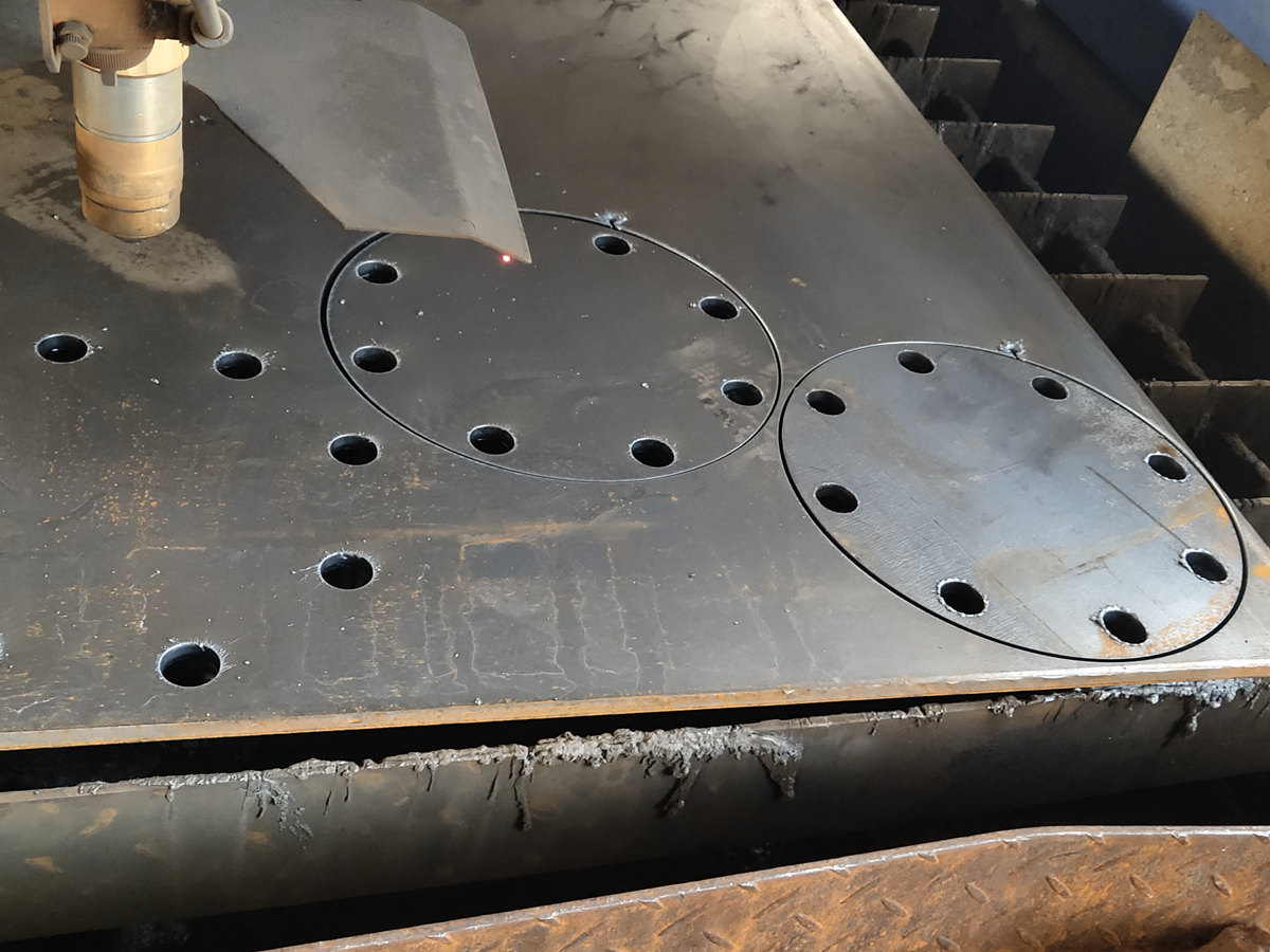
The most common plasma cutting defects affect the cut edge, hole geometry, part flatness, and repeatability. Dross can remain on the lower edge. Edge taper can change the fit of brackets and plates. Heat input can distort thin sheet. Poor pierce settings can damage hole starts. Arc instability can create inconsistent kerf width along the profile.
These issues matter because a plasma-cut blank is often only one production stage in a larger fabrication route. If the cut edge later needs metal bending, welding, powder coating, or assembly, the original cutting defect can move downstream and become a fit, finish, or inspection problem.
Plasma cutting issue | Likely process cause | Part feature affected | RFQ action for the buyer |
|---|---|---|---|
Dross or slag on the lower edge | Incorrect speed, current, gas flow, torch height, or material condition | Edges, weld preparation, coating adhesion | Define whether as-cut edges are acceptable or deburring is required |
Edge taper or poor squareness | Arc lag, worn consumables, incorrect torch alignment, thick plate behavior | Bolt plates, bracket edges, mating faces | Identify critical edges and any post-cut machining requirement |
Oversized or rough holes | Pierce damage, hole too small for the selected route, poor lead-in strategy | Bolt holes, slots, mounting patterns | Mark functional holes and inspection dimensions on the drawing |
Arc instability | Gas pressure variation, grounding issue, worn electrode, contaminated surface | Kerf width, profile consistency, surface marks | Confirm material surface condition and required edge appearance |
Heat distortion | High heat input, thin sheet, poor nesting, weak fixturing, long cut paths | Flatness, bend sequence, assembly fit | State flatness needs, bend lines, and downstream welding sequence |
Why does dross form during plasma cutting?
Dross forms when molten metal is not fully ejected from the cut path and then solidifies on the lower edge or cut surface. The root cause may be cutting speed, amperage, gas selection, torch standoff, consumable condition, material grade, plate thickness, or surface contamination.
The RFQ implication is clear: the buyer should state whether the part can ship with as-cut edges or whether the edge needs deburring, grinding, sandblasting, or coating preparation. Dross on a weld edge, threaded-hole area, sealing face, or cosmetic edge should be treated differently from dross on a noncritical scrap edge.
What causes edge taper and poor squareness?
Edge taper and poor squareness usually come from arc behavior, torch alignment, travel speed, plate thickness, nozzle wear, or incorrect parameter selection. Plasma cutting removes material with an arc rather than a rigid tool, so thicker materials and complex profiles can show more variation between the top and bottom edge.
Buyers should identify which edges are functional. A noncritical outside profile may tolerate more visible taper than a bolted mounting face or assembly datum. If an edge must locate another component, the supplier may plan secondary machining, grinding, or a different cutting route such as laser cutting for selected features.
Why do arc instability and torch-height variation matter?
Arc instability and torch-height variation can change kerf width, edge texture, and profile repeatability. Common causes include unstable gas supply, worn consumables, poor grounding, warped material, dirty surfaces, incorrect standoff, or inconsistent material thickness.
For RFQs with repeated brackets, frames, and equipment panels, buyers should provide clean CAD geometry and identify critical dimensions. If the supplier knows which holes, slots, and outside edges are functional, the plasma cutting program can prioritize stable lead-ins, pierce locations, nesting, and inspection points.
How do material thickness and gas settings create cutting issues?
Material thickness and gas settings influence heat input, cut speed, oxidation, edge color, and dross behavior. Carbon steel, stainless steel, aluminum, copper, and brass do not respond the same way to plasma arcs. A setting that works for a carbon steel base plate may not suit an aluminum cover or a stainless steel guard.
The buyer should separate material families in the RFQ rather than grouping all parts under one generic cutting requirement. A mixed-material package should list grade, thickness, quantity, surface condition, and finish requirement for each part number. That information helps the supplier decide whether one sheet metal fabrication route can cover the full package or whether different cutting and finishing steps are needed.
How do heat distortion and heat affected zones affect parts?
Heat distortion and heat affected zones can affect flatness, bend accuracy, weld fit-up, coating appearance, and assembly alignment. Thin sheets can move during cutting. Long cuts can concentrate heat. Closely nested features can change local stress. Heat affected zones can also influence later drilling, tapping, welding, or surface finishing.
Buyers should provide flatness requirements, bend lines, weld locations, and cosmetic surfaces before quotation. If the part needs a controlled visual finish, the RFQ should include finishing steps such as powder coating or polishing. If the part has tight assembly dimensions, the supplier may add inspection after cutting or after secondary operations.
What inspection and finishing details help prevent rework?
Inspection and finishing details help prevent rework by defining what matters before the plasma cutting program is prepared. Buyers should identify critical-to-function dimensions, hole patterns, mating faces, weld edges, cosmetic sides, burr limits, flatness needs, and any final inspection report requirements.
For functional metal parts, dimensional checks may include calipers, gauges, templates, or coordinate measurement depending on the drawing requirement. If the drawing requires a formal dimensional report, buyers should state that requirement in the RFQ. The same applies to finish acceptance, because a bracket hidden inside an assembly and a visible equipment cover should not be quoted with the same edge and surface expectation.
Related FAQs
How can manufacturers minimize dross formation during plasma cutting?
What common mistakes lead to excessive waste in plasma cutting operations?
How can plasma cutting precision be improved in manufacturing?
Can plasma cutting achieve tight tolerances for complex custom parts?
How important is nesting software in minimizing plasma cutting waste?
What are common challenges manufacturers face when implementing plasma cutting?
How does plasma cutting technology achieve precision and reduce material waste?