What common mistakes lead to excessive waste in plasma cutting operations?
Common mistakes that lead to excessive waste in plasma cutting include using outdated drawings, applying one parameter set to different metals, poor nesting, unclear edge requirements, weak consumable control, poor material handling, and missing inspection criteria. For buyers quoting brackets, frames, guards, panels, base plates, and weldment blanks, the practical RFQ problem is whether the plasma cutting route prevents avoidable scrap, rework, dross removal, wrong-revision parts, and rejected features.
Which plasma cutting mistakes create the most waste?
The most wasteful mistakes usually happen before the torch starts. Wrong CAD files, outdated drawings, unclear critical dimensions, poor nesting, and missing material details can create scrap even when the cutting machine is working correctly. Process mistakes then add more waste through dross, bevel, heat distortion, rough holes, and rejected edges.
Waste should be evaluated as material, time, labor, and downstream rework. A blank that needs unexpected grinding, drilling, coating repair, or re-cutting has already consumed capacity. Clear RFQ data and controlled production steps reduce that risk.
Common mistake | Waste mechanism | Part feature affected | Prevention step |
|---|---|---|---|
Wrong drawing or CAD revision | Parts are cut to obsolete geometry | All profiles, holes, slots, bend lines | Use released drawings, revision control, and clean CAD files |
Generic cutting parameters | Settings do not match material or thickness | Dross, kerf width, bevel, heat affected zone | Separate carbon steel, stainless steel, aluminum, copper, and brass requirements |
Poor nesting | Material layout creates scrap or heat concentration | Batch yield, flatness, part orientation | Confirm quantity, kit grouping, sheet size, and cosmetic direction |
Worn consumables | Arc instability repeats defects across the batch | Hole quality, edge texture, profile repeatability | Track nozzles, electrodes, gas supply, and first-article results |
Unclear finishing and inspection | Parts are cut without knowing the final acceptance standard | Edges, weld areas, coating surfaces, datums | Define deburring, coating, machining, and inspection requirements early |
How do wrong drawings and poor CAD data create waste?
Wrong drawings and poor CAD data create waste because plasma cutting depends on digital geometry. Duplicate lines, open contours, missing hole callouts, old revisions, or unclear part numbers can cause wrong parts to be cut before anyone notices the problem.
Buyers should send one released drawing package with matching CAD files and clear revision levels. If prototype and production versions both exist, the RFQ should separate them. This prevents obsolete blanks from entering bending, welding, coating, or assembly.
Why do wrong cutting parameters waste material?
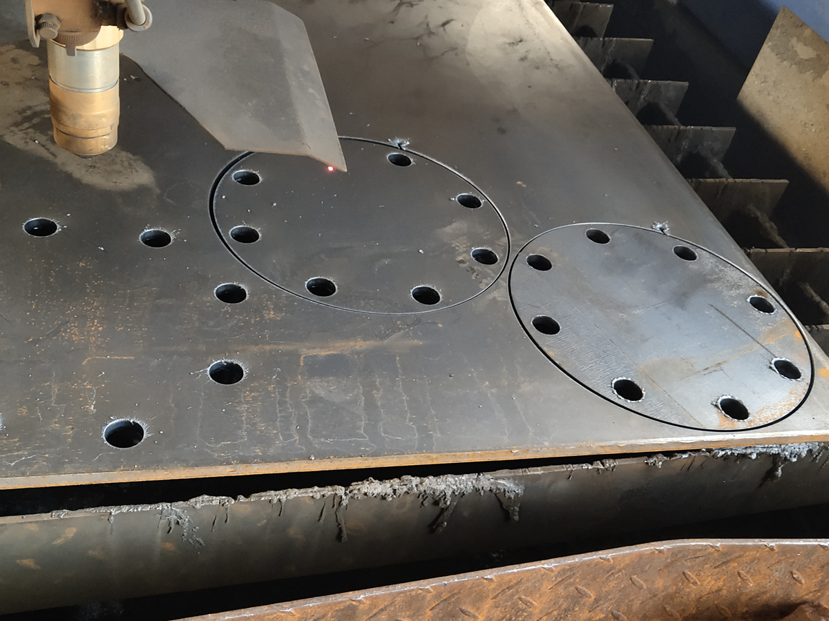
Wrong cutting parameters waste material by creating dross, wide kerfs, edge taper, heat distortion, rough pierces, and poor hole quality. Torch height, gas flow, amperage, speed, grounding, and material support must match the metal grade and thickness.
The buyer should identify material grade and thickness for each part number. A carbon steel bracket, stainless steel guard, aluminum cover, and copper plate should not be quoted as one generic metal group. Different materials need different process review and may need different finishing steps.
How does poor nesting increase plasma cutting waste?
Poor nesting increases waste by leaving avoidable offcuts, creating inefficient torch travel, concentrating heat, or orienting parts incorrectly. In repeated production, small layout problems can repeat across many sheets or plates.
For sheet metal fabrication projects, buyers should provide quantities, kit groupings, part orientation needs, cosmetic faces, grain direction if required, and any material size constraints. Better nesting starts with clearer production information.
How do material surface and handling mistakes create scrap?
Material surface and handling mistakes create scrap when rust, oil, coatings, poor flatness, wrong material, mixed batches, or surface contamination affect the arc or final finish. Coated or galvanized material may also require fume and safety review before cutting.
Buyers should disclose coatings, surface condition, material certificates, and any cosmetic requirements. Manufacturers should stage material by grade and thickness and protect visible surfaces when those surfaces matter to the final part.
Why do consumable and maintenance mistakes repeat defects?
Consumable and maintenance mistakes repeat defects because worn nozzles, electrodes, shields, unstable gas supply, poor grounding, and table issues can change cut quality during a batch. Once the process drifts, many parts may share the same edge or hole problem.
Manufacturers should use first-article checks and in-process monitoring for repeated parts. Buyers can help by defining which dimensions, holes, and edges are critical. This keeps inspection focused on features that can cause real waste if they drift.
How do unclear finishing and inspection requirements cause rework?
Unclear finishing and inspection requirements cause rework when parts are cut before the supplier knows the final edge, surface, and dimensional standard. Plasma-cut parts may need deburring, sandblasting, powder coating, drilling, tapping, machining, or inspection before acceptance.
A hidden bracket, a weld edge, and a visible enclosure panel should not share the same finish assumption. Buyers should define cosmetic faces, weld areas, coating requirements, and required inspection reports before the quote is finalized.
What RFQ checklist reduces plasma cutting waste?
A waste-reduction RFQ should include material grade, thickness, CAD files, released drawing revision, quantity, kit grouping, hole sizes, slot widths, critical edges, bend lines, weld locations, surface finish, cosmetic faces, machining allowance, and inspection requirements. These details help the supplier avoid wrong cuts and plan the complete route.
The simplest buyer decision is to define the accepted part, not just the cut shape. When the supplier knows the material, geometry, finish, and inspection standard, plasma cutting waste can be reduced at the source instead of corrected after parts are already cut.
Related FAQs
How important is nesting software in minimizing plasma cutting waste?
How does plasma cutting technology achieve precision and reduce material waste?
How can manufacturers minimize dross formation during plasma cutting?
What are common challenges manufacturers face when implementing plasma cutting?
How can plasma cutting precision be improved in manufacturing?
How is custom plasma cutting technology evolving to meet sustainability goals?
What are the main cost advantages of using plasma cutting in manufacturing?