What are common challenges manufacturers face when implementing plasma cutting?
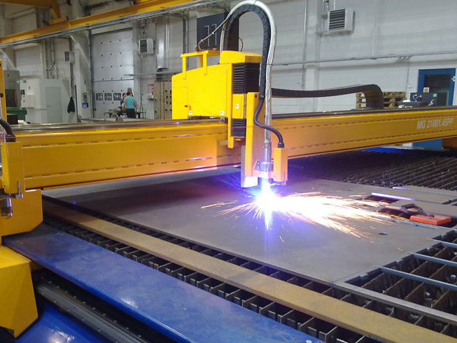
Common challenges when implementing plasma cutting include parameter setup, torch-height control, material distortion, dross, consumable wear, CAD/CAM nesting, operator training, post-cut finishing, inspection planning, and shop safety controls. For buyers and manufacturers working on brackets, frames, guards, panels, base plates, and weldment blanks, the practical RFQ problem is whether the plasma cutting route can control these risks across material selection, cutting, secondary operations, and final acceptance.
What implementation challenges appear first in plasma cutting?
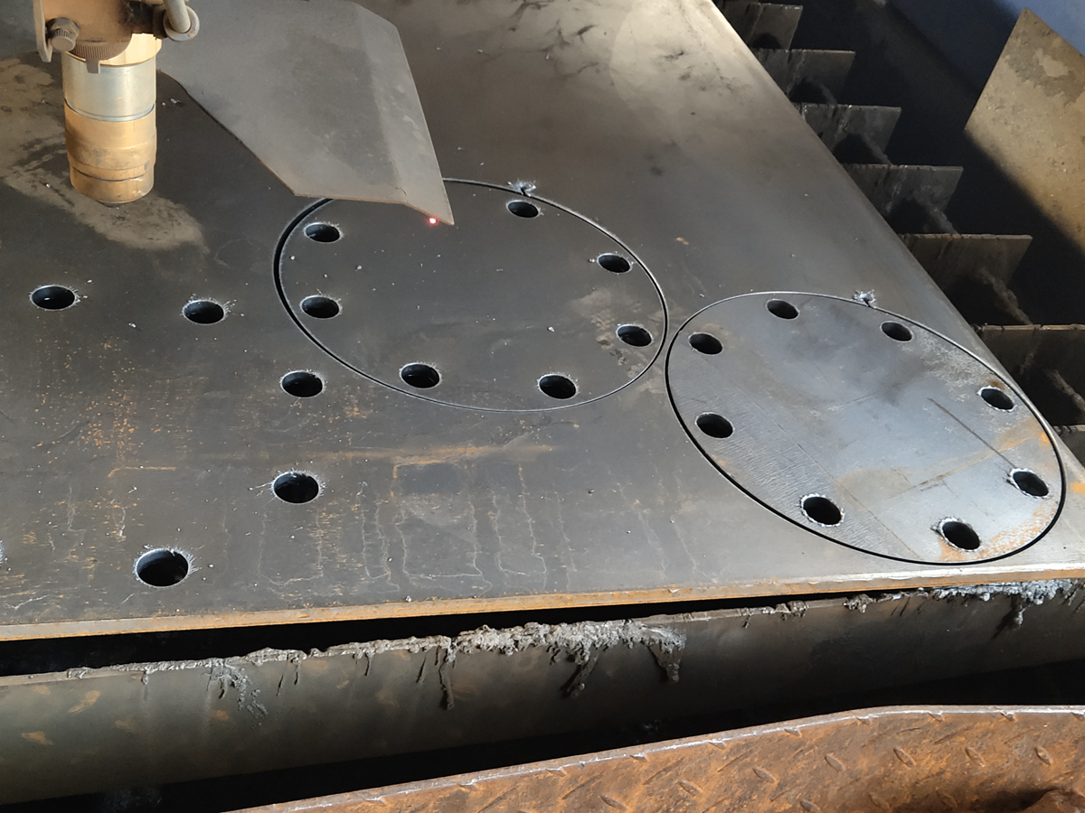
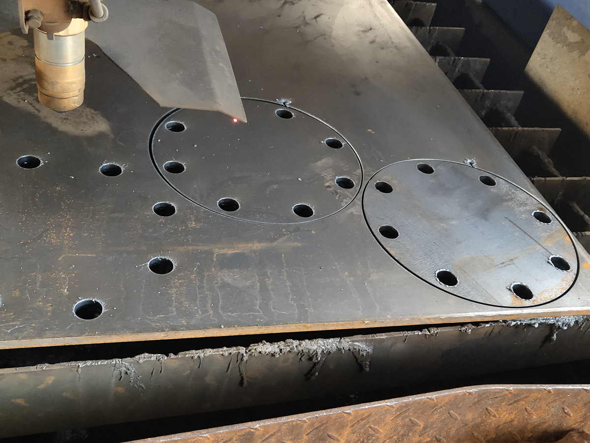
The first implementation challenges usually appear in setup. Torch height, cutting speed, amperage, gas flow, grounding, material support, pierce strategy, and lead-in placement must match the material and drawing. If these variables are not controlled, the parts can show dross, bevel, rough holes, arc instability, or heat distortion before downstream fabrication begins.
For manufacturers, the issue is repeatability. For buyers, the issue is quotation clarity. A supplier cannot correctly plan plasma cutting if the RFQ does not define material grade, thickness, critical dimensions, edge finish, bend lines, weld edges, coating needs, and inspection requirements.
Implementation challenge | Manufacturing risk | Part feature affected | RFQ or process control response |
|---|---|---|---|
Parameter setup | Wrong speed, power, gas, or torch height creates inconsistent edges | Kerf width, dross, bevel, holes | Match settings to material grade, thickness, and edge acceptance |
Material behavior | Different metals react differently to heat input | Flatness, heat affected zone, surface color | Separate carbon steel, stainless steel, aluminum, copper, and brass requirements |
Consumable wear | Worn nozzles and electrodes change arc stability | Profile repeatability, edge quality, pierce marks | Track consumable condition and inspect first articles |
Nesting and programming | Poor layouts increase scrap, heat concentration, and wrong cuts | Batch consistency, material use, part orientation | Use clean CAD data, revision control, and defined quantities |
Post-cut finishing | Unplanned cleanup delays the route or causes rejected parts | Edges, cosmetic surfaces, weld areas, coating adhesion | Define deburring, sandblasting, coating, machining, and inspection needs |
Why is process setup complex for plasma cutting?
Process setup is complex because plasma cutting is affected by the relationship between material, thickness, gas, power, torch standoff, pierce method, and cut path. A setting that works for a carbon steel plate may not suit a stainless steel guard, aluminum cover, copper plate, or brass part.
Manufacturers should control setup with documented parameters and first-article checks. Buyers should help by marking critical holes, slots, datum edges, and cosmetic faces. If the part will later move into sheet metal fabrication, the RFQ should include bending, welding, and finishing requirements before quotation.
How do material limitations and distortion create challenges?
Material limitations appear because plasma cutting requires a conductive workpiece and because each metal responds differently to heat. Carbon steel is usually straightforward for many fabrication jobs, while stainless steel may need more attention to heat tint and corrosion requirements. Aluminum can be sensitive to distortion. Copper and brass conduct heat quickly and can require careful process review.
Distortion becomes a challenge when thin sheet, long cut paths, tight nesting, weak fixturing, or later welding changes the part shape. Buyers should state flatness requirements, assembly datums, and bend lines. If heat affected zones are not acceptable, the supplier may compare plasma cutting with laser cutting, machining, or another route.
Why do consumable wear and maintenance affect implementation?
Consumable wear affects implementation because electrodes, nozzles, shields, and gas components influence arc shape and stability. Worn consumables can create wider kerfs, rough edges, poor pierces, and inconsistent profiles. Maintenance also affects grounding, gas flow, table condition, and material support.
For repeat production, manufacturers should monitor consumable life and inspect early parts in each run. Buyers can support this by defining acceptance criteria for edge condition, holes, and flatness. When requirements are clear, the supplier can decide where inspection should happen: after cutting, after deburring, after bending, or after coating.
How do post-processing and surface finish create hidden work?
Post-processing creates hidden work when dross, burrs, heat tint, or rough edges are not considered during quotation. Plasma-cut parts may require deburring, sandblasting, powder coating, polishing, machining, or weld preparation before the part is acceptable.
The buyer should define whether the part is an as-cut blank or a finished component. A hidden bracket may allow a different edge standard than a visible equipment cover. A weld edge may need different preparation than a coated cosmetic edge. Clear finishing requirements prevent underquoting and reduce rework.
How do CAD/CAM, nesting, and training affect plasma cutting results?
CAD/CAM, nesting, and training affect results because plasma cutting depends on digital geometry and disciplined shop execution. Poor file cleanup, outdated drawings, bad lead-in positions, weak nesting, and unclear cut sequencing can waste material or create thermal distortion even when the machine is capable.
Manufacturers should use controlled drawing revisions, verified CAD files, and trained operators who understand material behavior and inspection feedback. Buyers should supply clean files, quantities, material groups, and kit structure. This reduces avoidable scrap from wrong revisions, poor orientation, or inconsistent part grouping.
What safety and environmental controls should be planned?
Plasma cutting implementation should include controls for fumes, ventilation, eye protection, grounding, fire risk, hot parts, gas handling, noise, and material-specific hazards. Coated metals, oily surfaces, galvanized materials, or unusual alloys may require additional review before cutting.
Buyers should disclose coatings, surface treatments, material certificates, and any restricted substances or cleanliness requirements. Manufacturers should confirm that the cutting route, finishing route, and material handling route are suitable for the shop environment and the final application.
What RFQ details reduce plasma cutting implementation risk?
A strong RFQ should include material grade, thickness, CAD files, drawing revision, quantity, toleranced features, hole sizes, slots, bend lines, weld edges, cosmetic surfaces, finishing requirements, inspection method, and any safety or documentation requirements. This information helps the supplier identify setup risk before cutting begins.
The best implementation outcome comes from treating plasma cutting as one stage in a complete manufacturing route. When cutting, deburring, forming, welding, coating, inspection, and final validation are defined together, the process can be selected around the real part requirement instead of around a generic cutting capability.
Related FAQs
What common mistakes lead to excessive waste in plasma cutting operations?
How can manufacturers minimize dross formation during plasma cutting?
How can plasma cutting precision be improved in manufacturing?
How important is nesting software in minimizing plasma cutting waste?
How is custom plasma cutting technology evolving to meet sustainability goals?