How to lightweight tool housings through design and processes while keeping strength?
Lightweight tool housings should remove mass from low-stress areas while keeping strength at motor mounts, bearing seats, gear supports, hinge points, latch features, screw bosses, impact corners, and user grip interfaces. This FAQ explains how Neway reviews metal injection molding, plastic injection molding, aluminum die casting, overmolding, metal inserts, ribbed structures, surface finishing, and validation for power tool housings, lock housings, portable device frames, and high-strength internal supports. The practical RFQ problem is to define load paths, drop risk, fastener loads, material zones, and test requirements before the buyer chooses a lightweight manufacturing route.
Which load paths should stay reinforced in lightweight tool housings?
Buyers should keep material and reinforcement around the main load paths before reducing housing weight. Motor reaction forces, gear impact loads, handle loads, battery latch loads, drop corners, screw bosses, bearing seats, and locking features often control housing durability.
A lightweight housing should be reviewed as a functional structure, not only as an exterior shell. For power tools and locking systems, the housing may hold a motor, gearbox, MIM gear, stamped spring, metal latch, battery interface, cable outlet, and overmolded grip. The RFQ should identify which areas support loads, which areas are cosmetic, and which areas can be opened, pocketed, ribbed, or switched to another material.
Housing load path entity | Failure risk if over-lightened | RFQ control input |
|---|---|---|
Motor and gearbox supports | Misalignment, vibration, noise, and gear wear | Motor load, gear load, datum surfaces, and assembly tolerance |
Screw bosses and inserts | Cracking, stripping, and clamping force loss | Fastener size, torque, insert requirement, and boss geometry |
Drop corners and ribs | Corner fracture and rib root cracking | Drop height, impact direction, rib layout, and material choice |
Grip and latch interface | Loose grip, latch failure, and poor user handling | Overmold material, latch cycle target, and ergonomic requirement |
How can ribs, wall thickness, and pocketing reduce weight without losing strength?
Ribs, controlled wall thickness, gussets, boxed sections, and hollow pockets reduce weight when they follow the real load path. Uniform wall thinning can create weak bosses, sink marks, warpage, or poor impact response if the load path is not reviewed.
Design review should check rib height, rib thickness, rib root radius, screw boss support, wall transitions, latch pockets, draft, undercuts, and assembly clearance. For molded housings, plastic injection molding can support ribbed shells and ergonomic covers. For metal frames, aluminum die casting can support lightweight structural housings with bosses, ribs, and machined datum areas. Neway reviews geometry with tooling, flow, shrinkage, ejection, machining, and inspection in mind.
Which process and material zones fit lightweight tool housing design?
The process route should be chosen by housing zone. A single material may not solve every strength, weight, cost, grip, and impact requirement in a tool housing or lock housing.
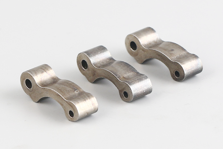
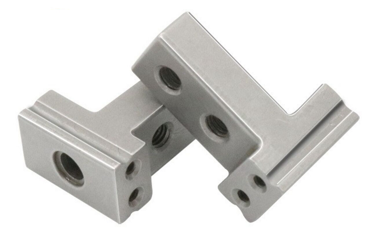
Metal injection molding can support small high-strength metal features, inserts, latches, gears, lock parts, and complex internal supports. Engineering plastics can support shell sections, insulation, and cosmetic features. Aluminum die casting can support structural frames or heat-spreading sections. Overmolding can support grips, seals, soft-touch zones, and cable strain relief. The buyer should define the function of each zone before Neway compares MIM, plastic injection molding, die casting, and overmolding.
Housing zone | Possible process route | Buyer decision affected |
|---|---|---|
High-load latch or lock component | MIM steel, stainless steel, or secondary heat treatment route | Strength, wear, tolerance, and production volume |
Outer shell and insulation area | Plastic injection molding with engineering thermoplastic | Weight, electrical insulation, appearance, and cost |
Frame or heat-spreading area | Aluminum die casting with machined datum surfaces | Stiffness, heat path, machining, and assembly accuracy |
Grip, seal, or shock absorption area | Overmolding or elastomer component | Ergonomics, vibration damping, sealing, and impact response |
How do MIM metal inserts and small components support lightweight housings?
MIM metal inserts and small components can reinforce local load points without turning the entire housing into a metal casting. This helps the buyer keep plastic or hybrid housing weight down while protecting wear, fastening, locking, and gear interfaces.
Potential MIM materials include MIM 17-4 PH, MIM 316L, MIM 4140, and MIM 8620, depending on corrosion, strength, wear, and heat treatment needs. MIM components should be reviewed for sintering shrinkage, density, datum surfaces, secondary machining, heat treatment, and assembly method. The buyer should mark which MIM part is load-bearing and how it is retained inside the housing.
How do surface treatment and validation protect lightweight housing durability?
Surface treatment and validation protect durability by checking wear, corrosion, grip wear, latch cycling, impact, and assembly stability after the housing has been lightened. Reduced wall thickness or hybrid material zones should be tested in the final assembly condition.
Surface finishing may include coating, polishing, passivation, plating, painting, texture, or anti-wear treatment depending on the housing zone. Prototyping can help verify drop behavior, screw boss strength, latch cycles, grip adhesion, vibration, and assembly alignment before tooling release. Validation should state sample quantity, drop direction, load case, fastener torque, environmental exposure, and pass criteria.
What RFQ details help Neway lightweight tool housings?
An RFQ should include 3D CAD, 2D drawings, target weight, load path map, drop requirement, motor or gearbox load, fastener torque, latch cycle target, material preference, metal insert requirement, overmold requirement, surface finish, cosmetic requirement, environmental exposure, sample quantity, production volume, and validation method. These inputs let Neway compare MIM inserts, plastic injection molded shells, aluminum die cast frames, overmolded grips, and secondary operations as one housing strategy.
The buyer should also identify the main tradeoff: weight, strength, impact resistance, grip comfort, cost, corrosion resistance, or production volume. That priority helps Neway decide where to remove material and where to keep reinforcement.
Related FAQs
How to balance weight reduction with adequate strength in lightweight tool design?
What lightweight materials offer strong anti-prying and impact resistance?
What material and process combinations help prevent prying and brute-force attacks?
What materials and processes suit high-impact environments with frequent drops?
How to design locks that balance weight reduction with strength and durability?
Can Neway supply a full lock component solution from prototype to mass production?
How does Neway assist in designing and prototyping MIM parts?
What quality inspection methods are used for tight-tolerance MIM components?