How to choose substrates for high-power LEDs balancing heat, insulation, and cost?
High-power LED substrate selection should balance heat spreading, electrical insulation, mechanical support, assembly method, environmental exposure, and production cost before the buyer locks the lighting module design. This FAQ explains how ceramic injection molding, aluminum die casting, ceramic substrates, aluminum IMS, copper-based substrates, surface finishing, and prototype testing apply to LED boards, COB modules, heat spreaders, reflector bases, insulated standoffs, and lighting thermal assemblies. The practical RFQ problem is to decide which substrate route can meet the LED heat path and insulation requirement without adding unnecessary manufacturing cost or validation risk.
What substrate requirements should buyers define first?
Buyers should define LED power, heat source area, target junction temperature, electrical insulation requirement, creepage and clearance needs, substrate size, heatsink interface, assembly load, environmental exposure, and cost target. These details determine whether aluminum IMS, copper-based substrates, or ceramic substrates should be reviewed.
For lighting solution, consumer electronics, and outdoor telecommunication hardware, the substrate is part of the thermal path and the electrical insulation system. A substrate that spreads heat well may still fail the design if dielectric strength, surface finish, mounting flatness, or environmental stability is not defined.
Substrate decision entity | Buyer question | Manufacturing implication |
|---|---|---|
Heat source area | How concentrated is the LED heat load? | Controls whether heat spreading or direct thermal path is the main risk |
Electrical insulation | What voltage and creepage requirement applies? | Controls dielectric layer, ceramic choice, and interface design |
Heatsink interface | How flat and stable must the substrate-to-heatsink contact be? | Controls machining, surface finishing, TIM, and inspection plan |
Production cost | Which performance requirements are fixed and which can be adjusted? | Controls whether aluminum IMS, copper, or ceramic is practical for the volume |
When does aluminum IMS fit high-power LEDs?
Aluminum IMS can fit LED modules where heat spreading, electrical insulation, cost control, and scalable production must be balanced. Aluminum IMS is often reviewed when the LED heat load can be managed through a metal base, dielectric layer, thermal interface material, and heatsink.
Aluminum die casting can support the surrounding heatsink or housing when fins, mounting bosses, and thermal pads need to be integrated. The buyer should define the interface flatness, coating, corrosion exposure, and thermal interface material because the substrate alone does not determine module temperature.
When should copper-based substrates be reviewed?
Copper-based substrates should be reviewed when a concentrated LED heat source needs stronger heat spreading than the aluminum route can provide under the buyer's size, weight, and temperature constraints. Copper can improve heat spreading, but copper also changes weight, cost, corrosion protection, and joining requirements.
The RFQ should identify whether copper is needed only under the LED die, across the full module, or inside a hybrid heat spreader. Buyers should also specify plating, soldering, bonding, corrosion exposure, and assembly stress. Without those inputs, the substrate comparison can understate the finishing and reliability work required by a copper-based route.
When do ceramic substrates support insulation and reliability?
Ceramic substrates should be reviewed when electrical insulation, heat-related dimensional stability, dielectric behavior, wear resistance, or environmental exposure is a major design requirement. Ceramic selection should be tied to the LED module's electrical and thermal stack, not only to a generic material ranking.
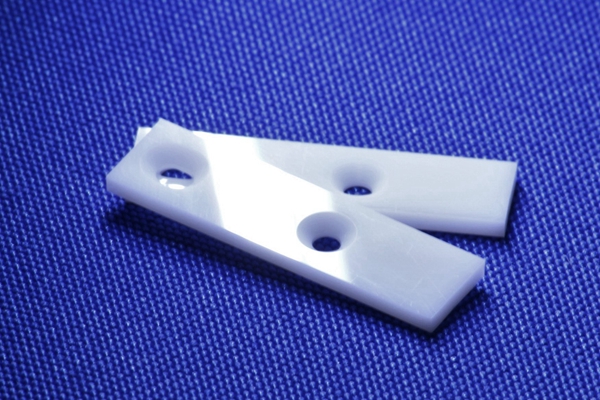
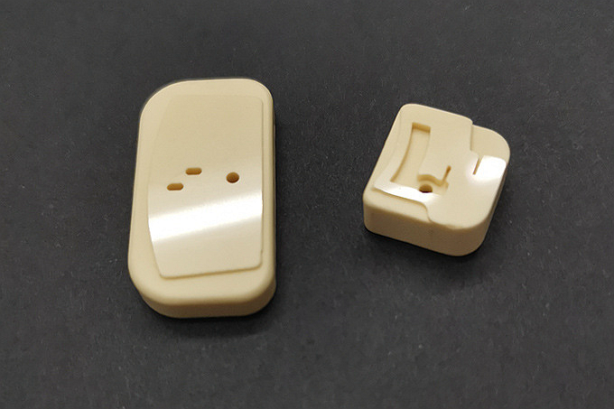
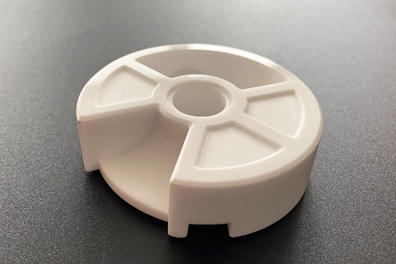
Alumina, silicon nitride, silicon carbide, and zirconia each bring different mechanical, dielectric, and thermal behavior. Ceramic injection molding may also be reviewed for 3D ceramic features such as insulated standoffs, reflector supports, alignment bosses, or ceramic housings around the LED module. The buyer should specify whether the ceramic part is the substrate itself or an adjacent ceramic thermal and insulation feature.
How do surface finish and TIM change substrate performance?
Surface finish and thermal interface material can change the measured performance of any substrate route. A high-conductivity substrate can still perform poorly if the contact surface is warped, coated incorrectly, contaminated, or paired with the wrong TIM thickness.
Neway reviews surface finishing, machining allowance, coating, and inspection requirements together with the substrate route. Aluminum housings may need controlled flatness and corrosion protection. Ceramic surfaces may need chipping control and clean contact areas. Copper-based parts may need corrosion and bonding controls. The buyer should define dimensions and roughness after finishing, not only before finishing.
What prototype tests support substrate selection?
Prototype tests should compare temperature rise, thermal resistance, dielectric strength, assembly fit, surface condition, coating response, and environmental stability. The comparison should use the same LED package, heatsink, TIM, airflow, and mounting condition for each substrate option.
Prototyping and CNC machining prototyping can support early heat spreader and heatsink trials before production tooling. Prototype data should feed the final substrate choice, substrate thickness, heatsink design, TIM selection, ceramic feature design, and production inspection plan.
Substrate route | Useful when | RFQ risk to define |
|---|---|---|
Aluminum IMS | Balanced heat spreading, insulation, and production cost are required | Dielectric layer, heatsink interface, coating, and TIM thickness |
Copper-based substrate | Localized heat spreading is the limiting design issue | Weight, corrosion protection, bonding, plating, and cost impact |
Ceramic substrate or ceramic interface part | Electrical insulation, dielectric behavior, or environmental stability matters | Ceramic material, shrinkage, surface condition, chipping risk, and assembly preload |
Aluminum heatsink or housing | The substrate must transfer heat into a larger enclosure or finned structure | Flatness, fin geometry, machining allowance, and surface finish |
What RFQ details help Neway compare LED substrate options?
A high-power LED substrate RFQ should include LED package data, heat load, board layout, target thermal resistance, insulation requirement, creepage and clearance requirement, substrate size, heatsink material, TIM requirement, surface finish, environmental exposure, production volume, prototype data, and test method. These details allow Neway to compare aluminum IMS, copper-based substrates, ceramic substrates, and related heatsink manufacturing around the same buyer decision.
The buyer should also identify which performance targets are fixed and which can be adjusted. That distinction helps Neway protect thermal and insulation requirements while reviewing manufacturability and production cost.
Related FAQs
How to control transmittance, haze, and refractive index accuracy in lenses?
What weather-resistant traits must outdoor optical parts have?
How does Neway control optical surface defects for lighting needs?
What support does Neway offer from optical simulation to prototype beam validation?
How to select thermal interface material between chip and heatsink?
Can aluminum die casting be used for heat dissipation components?
What parameters are vital for thermal design in high-power LED luminaires?
What tests should be performed on functional prototype parts?