How does Neway ensure defect-free optical surfaces for high-end lighting needs?
High-end lighting optical surfaces require defect control across material selection, ceramic injection molding, plastic injection molding, polishing, coating, and inspection. This FAQ explains how Neway reviews lenses, light guides, ceramic optical windows, protective covers, reflectors, and lighting module interfaces so buyers can define allowable surface defects, optical measurements, and validation requirements before RFQ. The practical RFQ problem is to convert a broad request for defect-free optical surfaces into measurable limits for haze, transmittance, scratches, flow marks, coating uniformity, profile accuracy, and assembly alignment.
Which optical surface defects should buyers define first?
Buyers should define visible defects, optical defects, coating defects, and assembly-related defects separately. A lighting lens or optical cover cannot be controlled from the phrase defect-free alone because each lighting application has its own allowed defect size, location, viewing distance, and measurement method.
For lighting solution projects, common optical surface risks include scratches, digs, haze, flow marks, weld lines, bubbles, sink marks, orange peel, tool marks, particulate contamination, coating color shift, coating pinholes, and surface waviness. The RFQ should identify critical optical zones, cosmetic zones, sealing zones, and mounting zones so Neway can apply the right inspection standard to each feature.
Optical surface defect entity | Lighting performance risk | RFQ control input |
|---|---|---|
Scratches and digs | Scattered light, visible marks, and reduced appearance quality | Allowed size, allowed location, viewing condition, and inspection method |
Haze and bubbles | Lower transmission, beam distortion, and inconsistent brightness | Haze limit, transmittance target, material grade, and molding condition |
Flow marks and weld lines | Optical streaks, stress concentration, and nonuniform beam output | Gate location, flow path, resin drying, and molding window |
Coating nonuniformity | Color shift, reflectance drift, and local durability risk | Coating stack, masked zones, thickness control, and adhesion test |
Which material and process route fits lighting optical surfaces?
The material and process route should match the optical function, heat exposure, impact requirement, weather exposure, dielectric requirement, and annual volume. The buyer should not select the process only from part appearance because the same lighting module may combine molded plastic optics, ceramic supports, coated surfaces, and metal heat sinks.
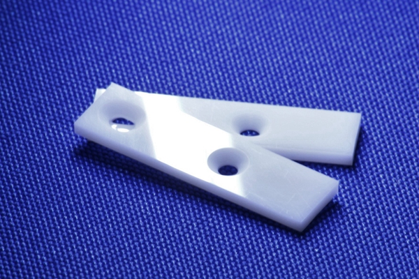
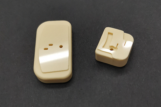
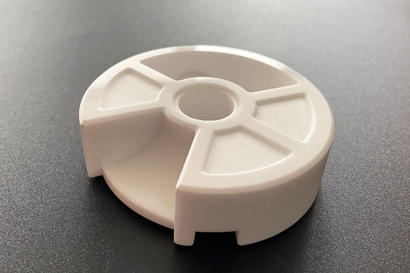
Plastic injection molding can support molded lenses, light guides, and transparent covers using PMMA, polycarbonate, or optical silicone rubber when the resin, drying condition, mold surface, and coating system are suitable. Ceramic injection molding can support ceramic optical-adjacent parts, holders, windows, insulators, and thermal or dielectric structures using alumina, zirconia, silicon carbide, or silicon nitride when the ceramic part must hold shape under thermal, mechanical, or environmental load.
How does tooling and molding control surface defects?
Tooling and molding control surface defects by stabilizing cavity finish, gate position, venting, flow balance, drying, temperature, pressure, cooling, and demolding. These controls reduce the sources of haze, weld lines, sink marks, trapped gas, stress marks, and surface waviness.
For molded plastic lighting optics, mold polish, runner layout, parting line position, ejection design, and handling can affect the optical zone. For ceramic injection molding parts, feedstock preparation, molding pressure, debinding, sintering shrinkage, and post-sintering finish can affect surface condition and dimensional fit. Neway reviews critical-to-optical surfaces separately from general mechanical surfaces so the process plan protects the beam path without adding unnecessary controls to noncritical features.
Manufacturing stage | Surface defect controlled | Buyer decision affected |
|---|---|---|
Mold design and polish | Tool marks, waviness, parting marks, and local texture mismatch | Optical zone map, parting line approval, and texture requirement |
Injection molding process | Flow marks, bubbles, weld lines, sink marks, and residual stress | Material route, gate position, wall thickness, and inspection samples |
CIM debinding and sintering | Surface contamination, shrinkage variation, cracking, and distortion | Ceramic material choice, datum plan, and post-sintering operation |
Handling and packaging | Scratches, fingerprints, particles, and coating damage | Clean handling rule, protective film, and final packing requirement |
How do polishing, PVD, and surface finishing support optical quality?
Polishing, PVD, and surface finishing should be specified by the optical function they protect. The buyer should identify whether the surface operation is needed for transmission, reflection, scratch resistance, cosmetic appearance, coating adhesion, or cleaning durability.
Polishing may be applied to mold surfaces, prototype samples, selected ceramic surfaces, or optical-adjacent features. PVD coating may be reviewed for thin-film layers where reflectance, color, or wear response matters. Surface finishing requirements should define coated areas, uncoated areas, edge masking, contact points, cleaning method, and final inspection condition.
Which inspection methods confirm lighting optical surface quality?
Inspection should combine optical measurement, dimensional measurement, surface inspection, and functional lighting validation. A single visual inspection cannot confirm transmittance, haze, refractive behavior, beam distribution, coating adhesion, and assembly alignment at the same time.
Typical checks may include transmittance and haze measurement, surface defect visual inspection, profile measurement, CMM dimensional inspection, optical comparator inspection, coating adhesion review, and prototype beam validation. Neway can use prototyping to compare material, tooling, surface finish, and coating choices before production tooling. For profile and dimensional checks, buyers may also review related methods such as optical comparator profile inspection and CMM dimensional inspection.
What RFQ details help Neway control optical surface defects?
An RFQ for high-end lighting optical surfaces should include 3D CAD, 2D drawings, material preference, optical zone map, wavelength range, transmittance target, haze limit, refractive index requirement, surface defect standard, coating stack, surface finish requirement, viewing condition, inspection method, assembly interface, sample quantity, and production volume. These details let Neway review material, tooling, molding, polishing, coating, and validation as one manufacturing route.
Buyers should also separate optical performance requirements from cosmetic requirements. This separation helps Neway focus tighter controls on the lens area, light guide path, reflective surface, or sealing interface while keeping the RFQ practical for production cost, lead time, and inspection workload.
Related FAQs
How to control transmittance, haze, and refractive index accuracy in lenses?
What support does Neway offer from optical simulation to prototype beam validation?
What weather-resistant traits must outdoor optical parts have, and how to achieve them?
How to choose substrates for high-power LEDs balancing heat, insulation, and cost?
What parameters are vital for thermal design in high-power LED luminaires?
How to balance lightweight design with thermal performance in lighting systems?
What tests should be performed on functional prototype parts?
What information should buyers provide for an accurate prototype quote?