What Is Sheet Metal Stamping? How Does It Work?
This article explains sheet metal stamping for buyers sourcing custom stamped metal parts such as brackets, clips, covers, shells, terminals, frames, contacts, and formed sheet components. The practical RFQ problem is deciding whether sheet metal stamping fits the material grade, sheet thickness, part geometry, bend and draw features, tolerance target, burr direction, surface finish, tooling budget, production volume, secondary operations, and inspection evidence.
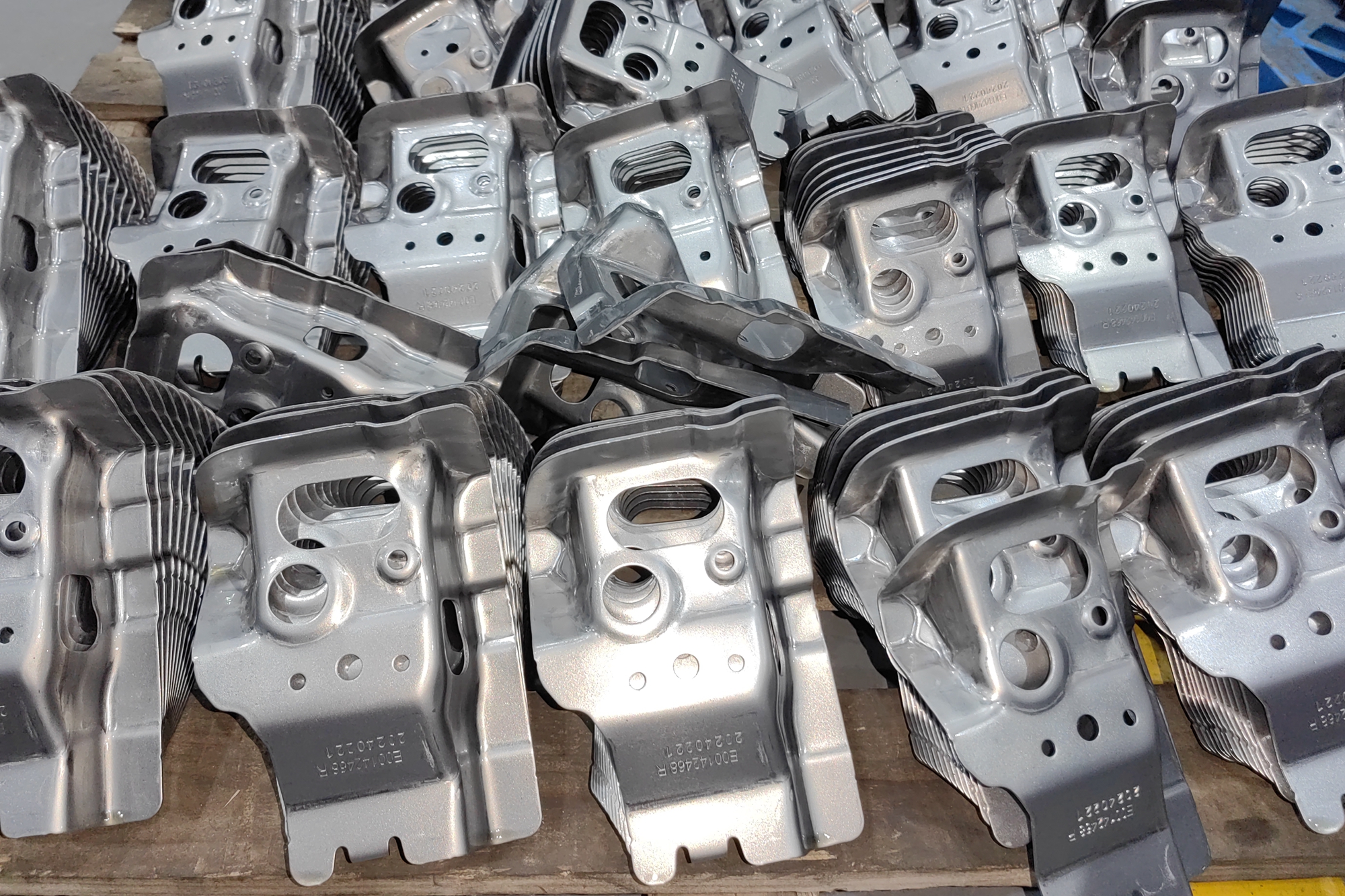
The short answer is that sheet metal stamping is suitable when the part can be formed from sheet or coil stock using a die and press, especially when production volume can justify dedicated tooling. Buyers should define the finished part, not only the flat blank, because cutting, piercing, bending, drawing, forming, deburring, plating, coating, and inspection can all affect the delivered component.
Neway supports related sheet metal stamping, sheet metal fabrication, and metal bending route reviews before quotation.
Sheet Metal Stamping RFQ Decision for Custom Metal Parts
Sheet metal stamping should be reviewed when the part is made from sheet stock and needs repeated cut, pierced, bent, drawn, coined, embossed, or formed features. The process can reduce unit cost at suitable volume, but the tooling investment, design constraints, and material behavior must fit the part.
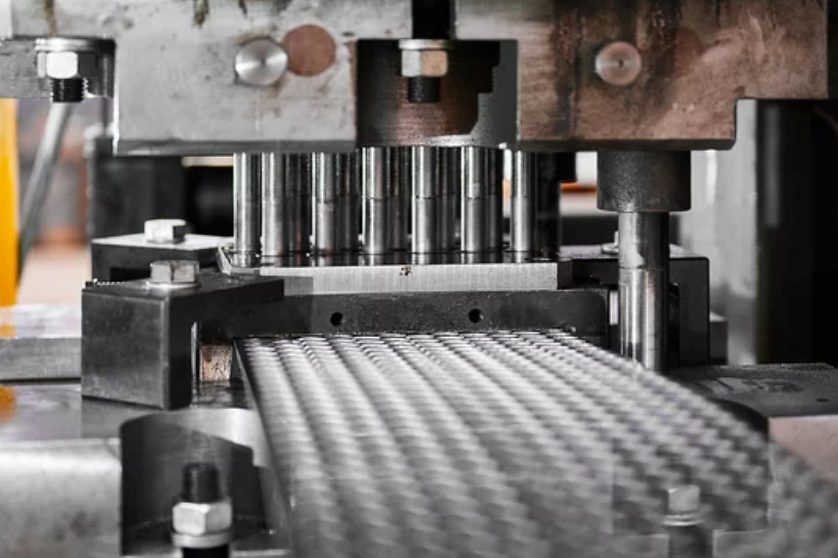
The manufacturing reason is that a punch and die shape the sheet in a press. The tool controls the cut edge, bend, draw depth, feature location, burr direction, and part repeatability. If the design needs complex forming or tight feature location, tooling design and material springback must be reviewed early.
Buyer Question | Stamping Answer | RFQ Information Needed |
|---|---|---|
Which parts fit stamping? | Brackets, clips, terminals, contacts, covers, drawn shells, frames, and formed sheet components | STEP file, flat pattern if available, 2D drawing, material grade, thickness, and annual volume |
Which features drive tooling? | Pierced holes, bends, draws, tabs, embosses, louvers, ribs, and tight feature locations | Feature map, critical dimensions, bend direction, burr side, and cosmetic surfaces |
Which risks affect acceptance? | Burrs, springback, cracking, wrinkling, thinning, tool marks, and coating damage | Defect limits, inspection method, surface finish, and secondary operation scope |
Which cost driver matters most? | Tooling cost, press setup, material yield, and production volume | Prototype quantity, batch size, annual demand, release schedule, and revision risk |
How Sheet Metal Stamping Works: Coil, Blank, Die, Punch, Press, and Ejection
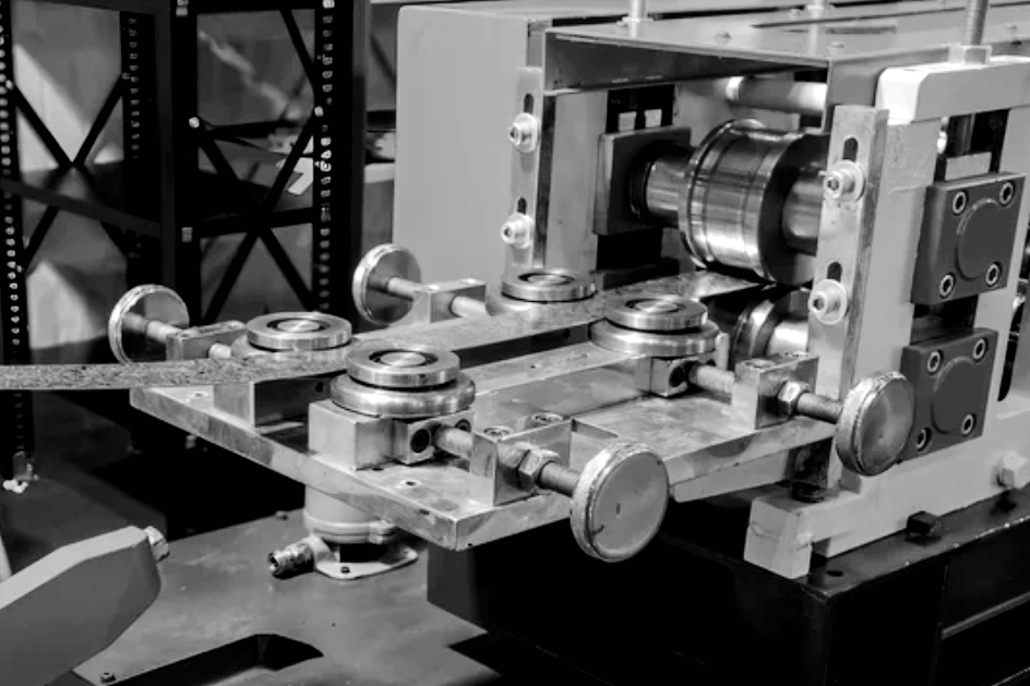
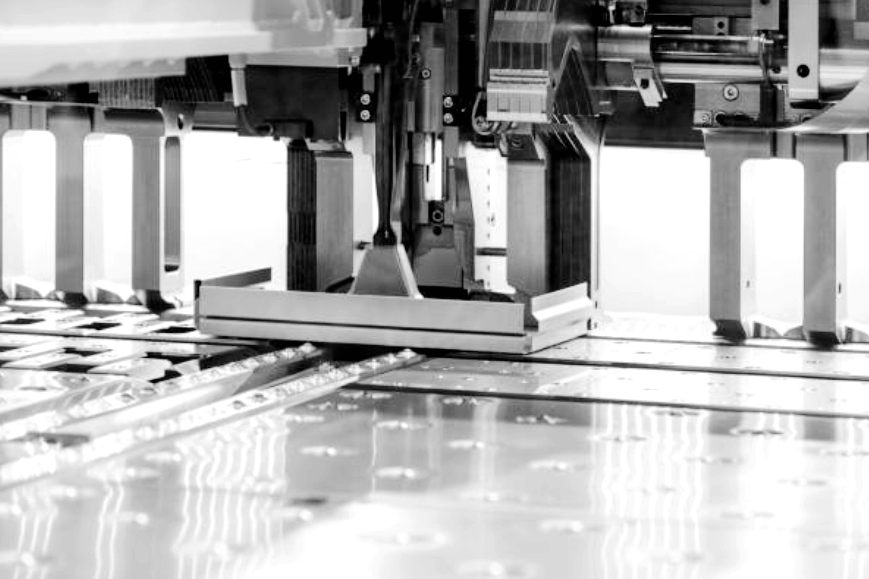
Sheet metal stamping starts with coil or sheet stock. The material is fed or placed into a die set, where the punch and die cut or form the part. The press applies force, the tool controls the shape, and the part or strip advances to the next operation.
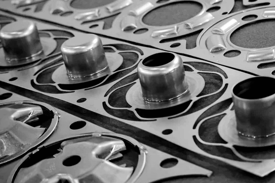
Common stamping operations include blanking, piercing, bending, drawing, forming, coining, embossing, trimming, and flanging. A finished stamped part may also require deburring, tapping, welding, plating, passivation, powder coating, cleaning, or assembly.
The RFQ implication is that buyers should identify the complete manufacturing route. A stamped bracket may need laser-cut prototypes first, progressive tooling later, and coating after forming. A drawn shell may need draw simulation, lubrication planning, and edge trimming. A contact part may need material grain direction and plating control.
Material Selection and Sheet Thickness for Stamped Parts
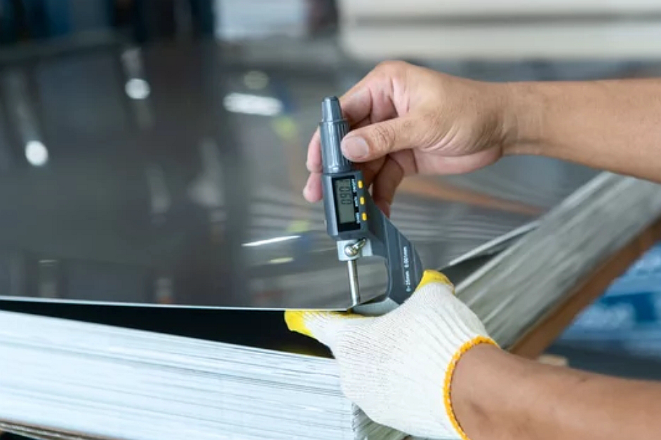
Material grade and sheet thickness strongly affect stamping. Stainless steel, carbon steel, aluminum, copper, brass, spring steel, and coated sheets all respond differently to blanking, bending, drawing, and forming. Material strength, ductility, springback, coating, surface finish, and grain direction should be reviewed before tooling.
The buyer should state the material grade, temper, thickness, coating, visible surface, corrosion requirement, conductivity requirement, and whether alternatives can be reviewed. Material changes after tooling can affect springback, cracking, burr, and final dimensions.
Progressive Die, Deep Drawn, Transfer Die, and Multi-Slide Stamping
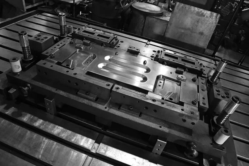
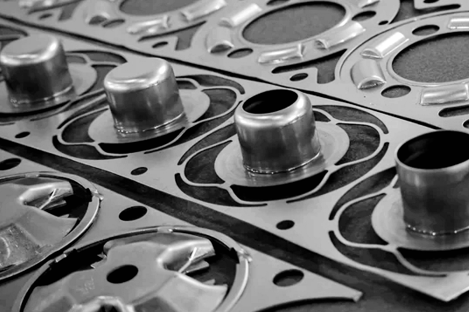
Progressive die stamping forms multiple features as the strip advances through several stations. It can be useful for high-volume repeat parts with pierces, bends, and formed features. Deep drawn stamping pulls sheet metal into a cavity to create cups, shells, cans, and housings with depth. Transfer die stamping moves individual parts between stations, which can help with larger or more complex formed parts. Multi-slide stamping uses multiple slides to form complex bends and small precision components from different directions.
The buyer decision depends on part geometry and volume. A small contact may fit progressive or multi-slide stamping. A deep shell may require draw analysis. A larger complex stamped part may need transfer tooling. The supplier should review the drawing and recommend the die strategy before tooling.
Design, Tolerance, Burr, Springback, and Defect Risks
Stamped part quality depends on design rules and material behavior. Minimum bend radius, hole-to-edge distance, slot width, feature spacing, draw depth, grain direction, and corner radii can all affect cracking, wrinkling, tearing, distortion, and springback.
Tolerances should be tied to function. Hole locations, bend angles, flatness, datum surfaces, and assembly features may need tighter inspection than nonfunctional edges. Burr direction should be defined when the edge contacts another part or when the stamped part will be handled manually.
The RFQ implication is that buyers should identify critical features and acceptable defect limits. The FAQ on defects of the metal stamping process can help define risk items before tooling.
Stamping Risk | Common Cause | Buyer Control |
|---|---|---|
Burrs | Punch clearance, tool wear, material thickness, or cutting direction | Define burr side, burr limit, and deburring requirement |
Springback | Material strength, bend radius, grain direction, and forming sequence | Provide angle tolerance, material temper, and functional bend surfaces |
Cracking or tearing | Small radius, poor material ductility, deep draw, or feature spacing | Allow radius review and confirm material grade before tooling |
Wrinkling or distortion | Draw depth, blank holder control, thin sheet, or uneven forming | Define cosmetic surfaces, flatness, and draw feature requirements |
Tooling, Volume, Secondary Operations, and Inspection
Stamping tooling should match the production volume and part maturity. Prototype parts may use laser cutting and press brake bending. Bridge production may use soft tooling. Stable high-volume parts may justify progressive, transfer, deep draw, or multi-slide tooling.
Secondary operations can include tapping, welding, riveting, hardware insertion, heat treatment, deburring, tumbling, cleaning, plating, passivation, painting, or powder coating. These steps should be included in the RFQ when the buyer needs a finished component.
Inspection can include dimensional reports, hole gauges, bend angle checks, flatness checks, burr inspection, surface review, coating thickness, and functional assembly checks. Tool maintenance and inspection plans help production remain stable across batches.
RFQ Checklist for Sheet Metal Stamping
A useful stamping RFQ should let the supplier evaluate material, die type, forming risk, secondary operations, and inspection before tooling begins.
RFQ Item | Why It Matters | Recommended Buyer Input |
|---|---|---|
Part files | Geometry drives die type, strip layout, forming sequence, and inspection | STEP file, 2D drawing, flat pattern if available, revision, and marked CTQ features |
Material and thickness | Controls springback, cracking, burrs, drawability, and surface finish | Grade, temper, thickness, coating, grain direction, and allowed alternatives |
Feature requirements | Holes, bends, draws, tabs, embosses, and louvers control tooling risk | Hole locations, bend angles, draw depth, burr side, visible surfaces, and datum plan |
Volume and schedule | Determines prototype tooling, soft tooling, or production die strategy | Prototype quantity, batch size, annual demand, ramp schedule, and revision risk |
Secondary operations | Finishing and assembly can change the manufacturing route | Deburring, tapping, welding, plating, coating, cleaning, packaging, and assembly notes |
Inspection evidence | Confirms the finished stamped part meets drawing and function | Dimensional report, gauge plan, visual criteria, surface report, and functional test |
Related FAQs