What Is Deep Drawn Metal Stamping? How Does It Work?
Deep Drawn Metal Stamping RFQ Decision for Hollow Sheet Metal Parts: Deep drawn metal stamping is a sheet metal forming process that turns a flat blank into a cup, shell, sleeve, can, enclosure, or other hollow part by pulling metal into a die cavity with a punch. This article explains how deep drawing works, when the route fits custom stamped parts, and what RFQ information buyers should provide to control wrinkling, wall thinning, cracking, trimming allowance, and inspection risk.
Deep drawing is different from simple bending or blanking because the material must flow from the flange area into the cavity without tearing or folding. A useful quotation needs more than an outside shape. The drawing should define material grade, sheet thickness, temper, draw depth, corner radius, functional surfaces, wall-thickness expectations, burr direction, trim edge, secondary operations, and inspection criteria before tooling review.
How Deep Drawn Metal Stamping Forms Flat Sheet Into Hollow Parts
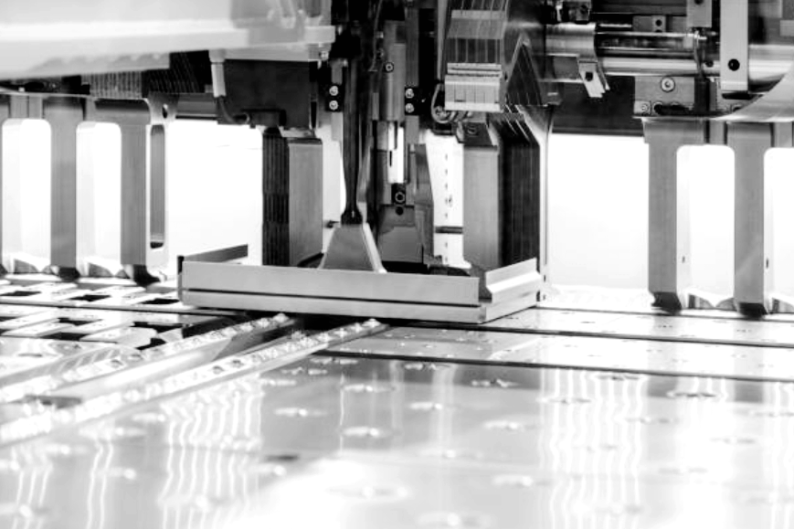
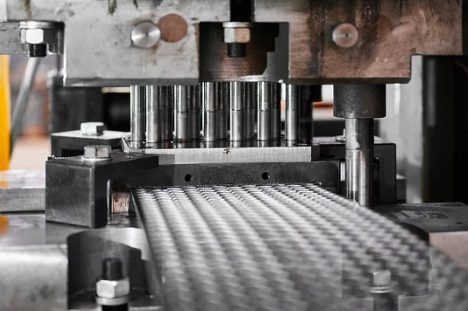
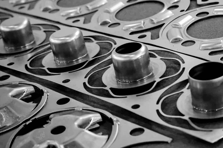
Deep drawn metal stamping forms a flat sheet blank into a three-dimensional part by controlling how the blank flows between the punch, die, and blank holder. The punch pushes the blank into the die cavity, while the blank holder restrains the flange enough to reduce wrinkling without stopping material flow. The die radius and punch radius guide the metal as the part wall forms.
The process may use one drawing operation or several redraw operations. A shallow cup may be formed in one draw, while a deeper shell may require multiple stages with intermediate trimming or annealing depending on the material and geometry. The exact route is subject to drawing review, material behavior, tooling design, and buyer acceptance criteria.
The main engineering question is whether the selected material can stretch and flow into the required depth without excessive thinning, cracking, earing, or surface damage. That is why material grade, temper, grain direction, lubrication, corner radius, and draw sequence are central to a deep drawing RFQ.
When Deep Drawing Fits Cups, Shells, Sleeves, and Enclosures
Deep drawn metal stamping is usually considered when a part needs a continuous wall, enclosed bottom, or shell-like shape made from sheet metal. Typical part families include cups, cans, sleeves, ferrules, housings, caps, covers, shields, battery cans, sensor shells, connector sleeves, and small containers. The process can be useful when a formed sheet metal part needs fewer joints than a welded assembly or when repeated production can justify drawing tooling.
Deep drawing is not the best choice for every hollow shape. Very sharp internal corners, severe depth changes, heavy wall-thickness demands, small radii in hard materials, and frequent design revisions may make the route difficult. In early development, buyers may need prototypes made by CNC machining, spinning, laser cutting with forming, or simplified tooling before committing to production draw tooling.
Deep Drawing Workflow From Blank Holder to Trimming
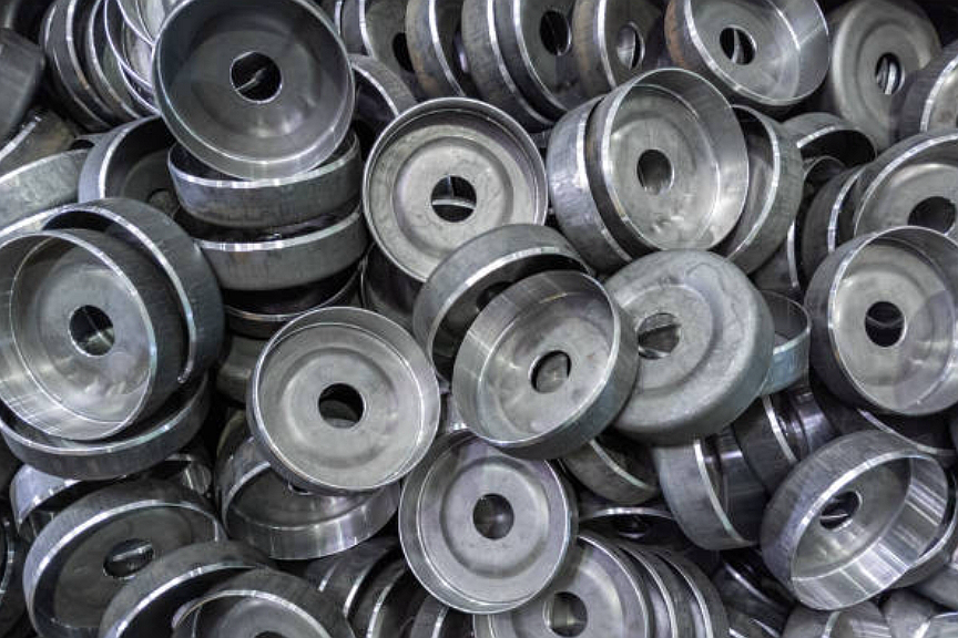
The deep drawing workflow begins with a blank size and drawing plan. The blank must contain enough material to form the wall and bottom while leaving allowance for trim edges, flange control, and any later operations. Tool design then defines punch geometry, die opening, blank-holder pressure, draw radius, lubrication method, and part removal.
During the draw, the blank holder controls the flange, the punch pulls material into the die cavity, and the wall forms as sheet metal flows around the die radius. If the part requires more depth, a redraw operation may reduce diameter and increase height in stages. After drawing, the part may be trimmed, pierced, flanged, deburred, cleaned, heat treated, plated, passivated, or assembled depending on the drawing requirements.
Process Stage | What Happens in Deep Drawing | Risk to Control | Buyer Requirement Needed |
|---|---|---|---|
Blank and material review | Material grade, sheet thickness, temper, and grain behavior are checked. | Low formability can cause cracking, earing, or excessive thinning. | Material specification, thickness, surface side, and certification needs if required by the buyer. |
Tooling and draw plan | Punch radius, die radius, blank-holder control, and draw sequence are planned. | Wrong radius or holding force can create wrinkles, splits, or surface marks. | Part depth, radius limits, wall-thickness concerns, cosmetic surfaces, and functional datums. |
Drawing and redraw | The blank is pulled into the die cavity and may pass through several redraw stages. | Wall thinning, uneven height, earing, and springback may affect final fit. | Critical dimensions, acceptable variation, mating parts, and inspection method. |
Trimming and piercing | Edges are trimmed and holes or slots may be added after forming. | Burrs, edge deformation, hole distortion, or datum shift may occur. | Trim edge function, burr side, hole function, and assembly requirement. |
Finishing and inspection | Parts may be deburred, cleaned, coated, plated, heat treated, or inspected. | Finishing can change appearance, dimensions, conductivity, or corrosion behavior. | Surface finish, coating thickness, packaging, traceability, and inspection records. |
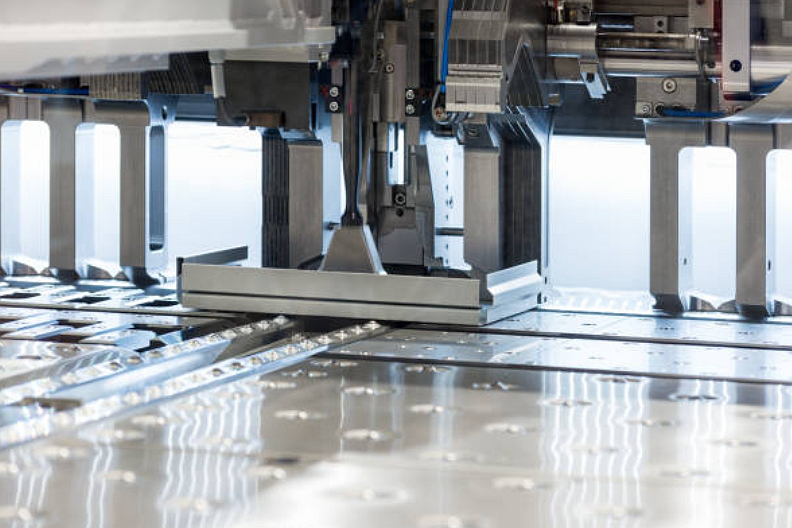
Punch, Die, Blank Holder, Radius, and Lubrication Controls in Deep Drawing
The punch, die, and blank holder control most deep drawing outcomes. The punch shapes the inside of the drawn part, the die shapes the outside path of material flow, and the blank holder controls the flange. If the blank holder restrains the flange too little, wrinkles can form. If the blank holder restrains the flange too much, the wall may thin or crack.
Radii are equally important. A radius that is too sharp can concentrate strain and cause cracking, while an oversized radius can reduce shape control or increase wrinkling risk. Lubrication helps the sheet flow into the cavity, but lubricant choice, cleaning requirements, and downstream finishing must be compatible with the final part requirements.
Buyers do not need to design every tooling detail, but buyers should identify functional surfaces, cosmetic surfaces, sealing edges, mating diameters, and areas that cannot accept tool marks. These requirements help the stamping supplier decide where forming marks, trim burrs, or handling marks may be acceptable and where tighter process control is needed.
Material and Geometry Risks in Deep Drawn Metal Stamping RFQs
Deep drawing depends strongly on material ductility and geometry. Low-carbon steel, stainless steel, aluminum, brass, copper, and some specialty sheet metals may be considered, but the material grade and temper must support the intended draw depth and radius. A material that machines well or bends acceptably may still be difficult to deep draw if elongation, work hardening, or grain behavior does not fit the part shape.
Geometry risks include wall thinning, cracking at corners, wrinkling in the flange, earing at the rim, springback, uneven trim height, and surface scratches. The RFQ should identify whether the bottom radius, side wall, rim, flange, and any pierced features are functional. If a hole, slot, or thread is needed after drawing, the drawing should specify whether the feature is pierced, drilled, tapped, riveted, welded, or assembled after forming.
Applications in automotive, electronics, industrial equipment, instrumentation, or regulated products should be discussed through buyer specifications, qualification requirements, and acceptance criteria. Final validation remains the buyer's responsibility, especially when the drawn part affects sealing, pressure containment, electrical function, safety, or regulatory approval.
Part Feature | Deep Drawing Risk | Quotation Impact | Inspection Evidence |
|---|---|---|---|
Deep cup or shell wall | Wall thinning, cracking, or redraw instability. | May require redraw tooling, formability review, or pilot validation. | Dimensional report, wall-thickness check, and visual inspection. |
Rim or trim edge | Earing, burrs, uneven height, or deformation during trimming. | May require trim allowance, deburring, or dedicated trimming operation. | Height measurement, burr standard, and edge visual check. |
Corner radius | Cracking, local thinning, or tool marks. | May require radius adjustment or different material temper. | Radius inspection, surface review, and functional fit check. |
Post-drawn holes or slots | Hole distortion, burrs, or datum shift after forming. | May require piercing after drawing or secondary machining. | Go/no-go gauge, optical inspection, or CMM check for selected features. |
Deep Drawing Compared With Progressive, Transfer, and Multi-Slide Stamping
Deep drawing is one stamping route, not a universal replacement for other forming methods. The best process depends on whether the part needs depth, a carrier strip, transfer handling, or multi-directional bending.
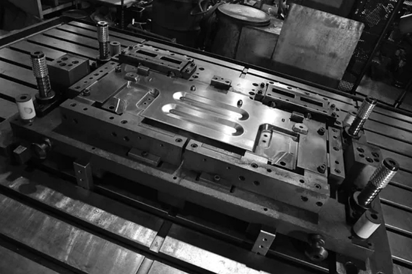
Deep Drawing vs. Progressive Die Stamping
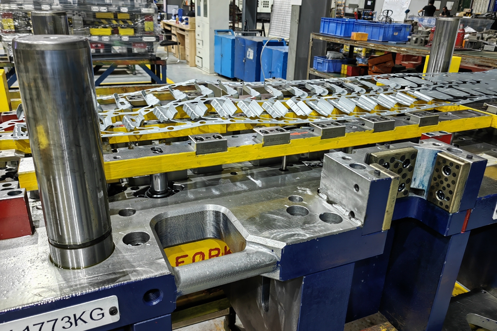
Progressive die stamping is usually better for flat or shallow formed parts that can stay attached to a strip while several stations add holes, bends, tabs, and cutoff features. Deep drawing is usually better when the main feature is a cup-like or shell-like form that requires controlled metal flow into a cavity.
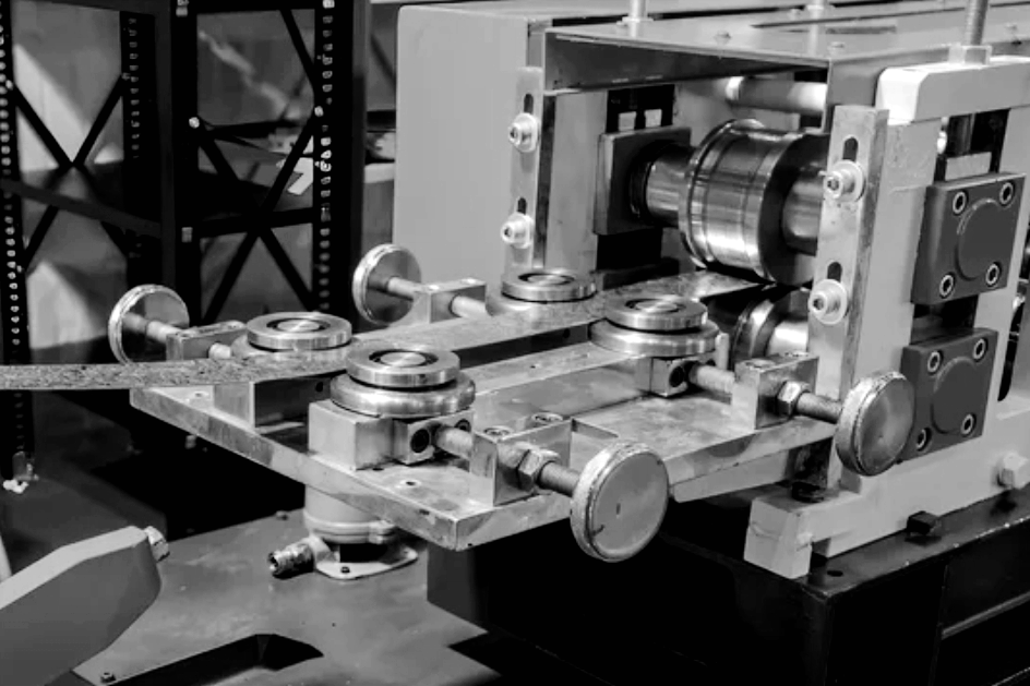
Deep Drawing vs. Transfer Die Stamping
Transfer die stamping can be useful when a part is too large or too three-dimensional to remain on a carrier strip. Some drawn parts may also use transfer handling between operations. The decision depends on part size, draw depth, station access, handling surfaces, and whether the formed part can be moved without damage.
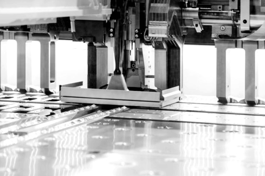
Deep Drawing vs. Multi-Slide Metal Stamping
Multi-slide metal stamping is generally considered for small clips, contacts, and components that need bends from several directions. Deep drawing focuses on pulling sheet metal into a cavity to create depth. If the part is a spring contact with several bends, multi-slide forming may fit better; if the part is a sleeve or shell, deep drawing may deserve review.
Inspection, Secondary Operations, and Documentation for Deep Drawn Parts
Inspection for deep drawn parts should focus on the features that affect assembly and function. Key checks may include overall height, outside diameter, inside diameter, bottom radius, wall thickness, trim height, flange shape, hole position, surface condition, burr direction, and cosmetic side. Depending on the drawing, inspection evidence may include first article inspection, dimensional reports, optical measurement, CMM checks for selected datums, go/no-go gauges, surface roughness checks, coating thickness reports, hardness checks after heat treatment, and visual standards for scratches or draw marks.
Secondary operations should be planned before tooling release. A deep drawn part may need trimming, piercing, flanging, deburring, cleaning, passivation, plating, anodizing, heat treatment, laser marking, welding, riveting, threaded inserts, leak testing, or assembly. Each operation can change dimensions, edge condition, or appearance, so the RFQ should describe the final part condition rather than only the drawn shape.
What Neway Precision Reviews Before Deep Drawing Tooling
For a deep drawing review, Neway Precision checks whether the material, geometry, draw depth, radius design, trim method, and secondary operations fit the intended manufacturing route. A complete RFQ normally includes a 2D drawing, 3D model if available, material grade and temper, sheet thickness, annual demand or production stage, functional datums, wall-thickness requirements, cosmetic surfaces, finishing requirements, packaging requirements, and inspection records.
If the design is not stable, a prototype or pilot route may be recommended before production tooling. Once the part function, material, and acceptance criteria are stable, deep drawn metal stamping can be reviewed as a production process for hollow sheet metal parts that need repeatable forming and controlled post-processing.
Related FAQs