What Is Multi-Slide Metal Stamping? How Does It Work? : A Comprehensive Guide
Multi-Slide Metal Stamping RFQ Decision for Small Formed Metal Parts: Multi-slide metal stamping is a sheet metal stamping process that uses several slides, cams, and forming tools to bend or shape strip-fed metal from multiple directions. This article explains how multi-slide stamping works, when the process fits clips, terminals, contacts, spring parts, small brackets, and retainers, and what RFQ details buyers should confirm before tooling review.
The practical decision is whether the part geometry benefits from side actions instead of a conventional straight press stroke. Multi-slide stamping can be useful when a small metal part needs several bends, offsets, hooks, lances, or spring features in different directions. Buyers should define material grade, thickness, temper, bend direction, functional contact areas, burr side, spring behavior, surface finish, and inspection needs before quotation.
How Multi-Slide Metal Stamping Forms Small Parts From Several Directions
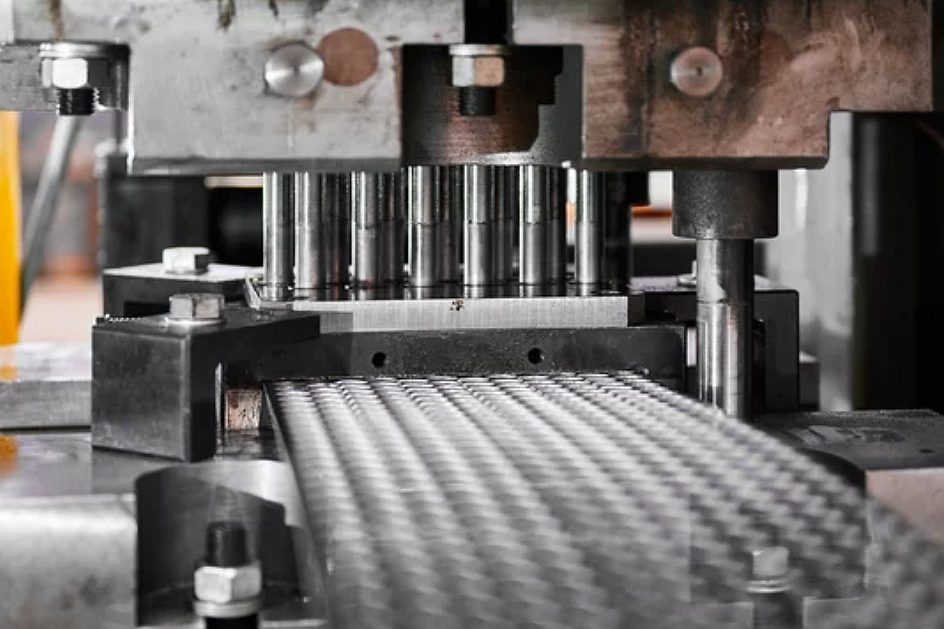
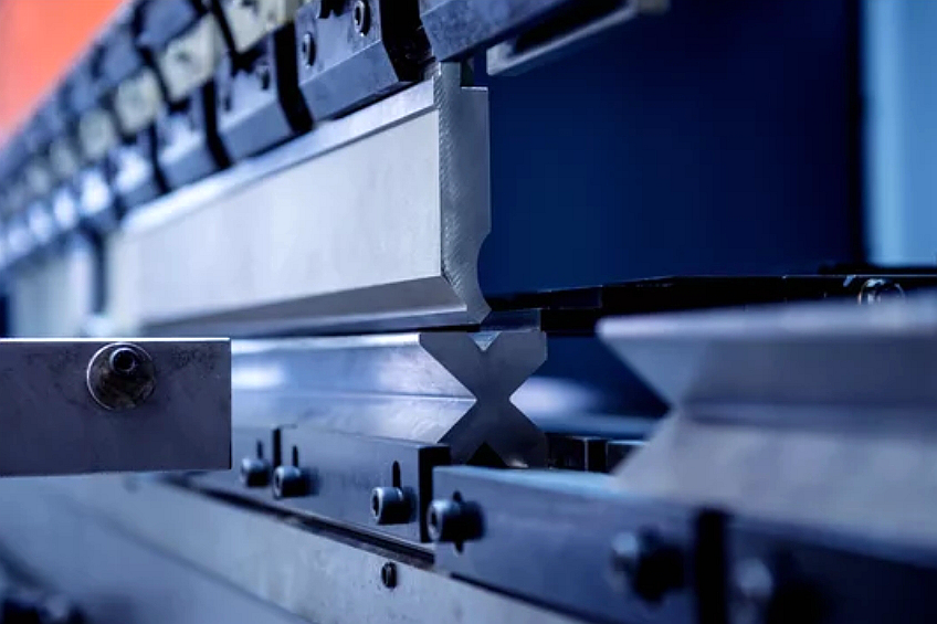
Multi-slide metal stamping forms a strip-fed workpiece by moving forming slides toward the part from different sides. Instead of relying only on an upper and lower die set, the process uses slide tools and cam actions to make bends, offsets, curls, tabs, and side forms. The strip advances through the machine, and forming actions occur in a controlled sequence until the part is cut off or separated.
The route is especially relevant when the part has multiple bends in different planes. A spring clip, electrical terminal, shield contact, retaining clip, or small latch may require one feature to bend upward, another feature to bend sideways, and another feature to hold a spring angle. Multi-slide tooling can create these features with coordinated side actions when the material and geometry are suitable.
The key manufacturing challenge is sequence control. If one bend is made too early, later tools may not reach the part. If a contact surface is used for support, handling marks may affect function. If springback is not considered, the final angle or contact force may drift from the drawing requirement.
When Multi-Slide Stamping Fits Clips, Contacts, Springs, and Small Brackets
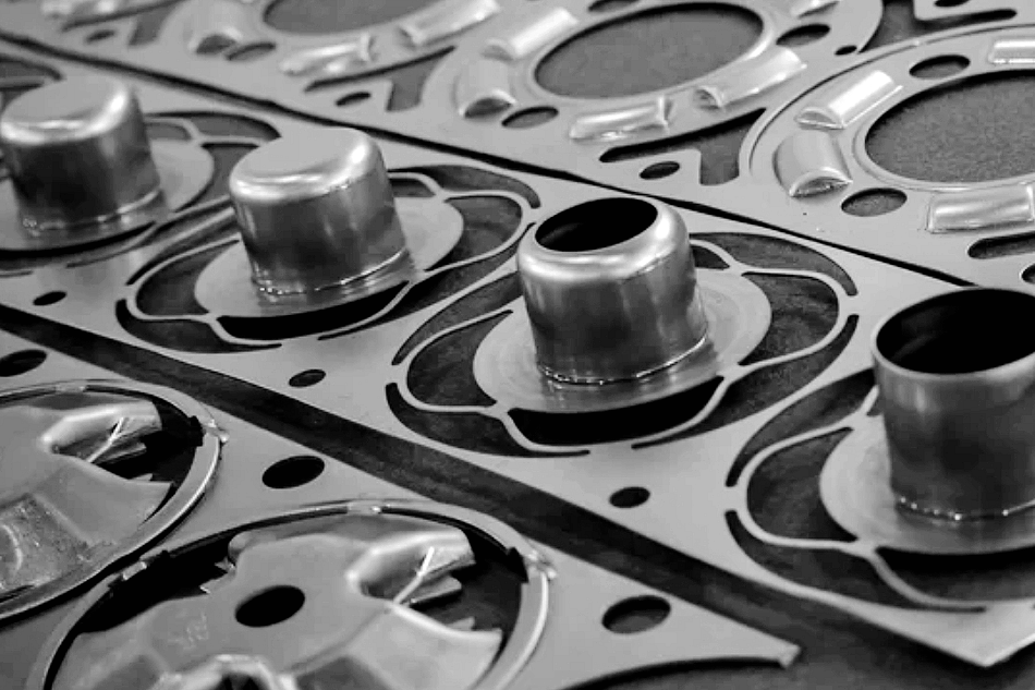
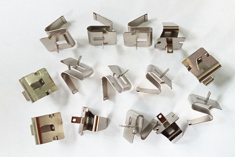
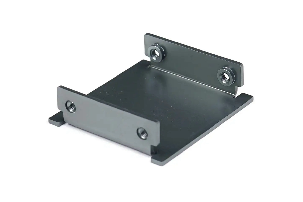
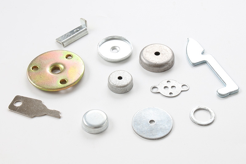
Multi-slide stamping is commonly reviewed for small metal components with complex bends, repeatable spring behavior, or features formed from several directions. Suitable part families may include spring clips, battery contacts, grounding contacts, connector terminals, retaining rings, small brackets, wire-form-like sheet parts, shields, latch parts, and compact mechanical fasteners.
The process may be less suitable for large panels, deep cups, heavy-gauge parts, or parts with broad flatness requirements over a large area. If the main requirement is many holes and shallow bends along a strip, progressive die stamping may be more appropriate. If the main feature is a cup or shell, deep drawn metal stamping may deserve review. If the part is larger and needs station-to-station handling, transfer die stamping may fit better.
Multi-Slide Stamping Workflow From Strip Feed to Cutoff
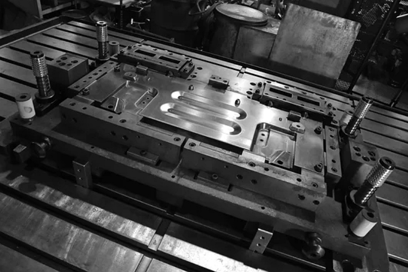
The multi-slide stamping workflow starts with the strip layout and forming sequence. Tooling engineers review the drawing to decide how the strip feeds, where pilot or locating features are needed, which bend happens first, how springback is controlled, and where cutoff occurs. The material strip then feeds through the tooling while slide actions form the part from different sides.
Each forming action must leave enough clearance for the next action. For example, a side bend may need to occur before a top form closes access. A tab may need to be pierced before bending. A spring contact may need over-forming to compensate for material springback, subject to material review and buyer acceptance criteria. After forming, the part is cut off and may move to deburring, heat treatment, plating, cleaning, or inspection.
Process Stage | What Happens in Multi-Slide Stamping | Risk to Control | RFQ Information Needed |
|---|---|---|---|
Part and strip review | The drawing, strip width, material grade, and bend directions are reviewed. | Wrong feed direction or strip orientation can make side forming difficult. | 2D drawing, 3D model, material specification, thickness, and grain direction if relevant. |
Slide and cam sequence | Tools are assigned to side actions, vertical actions, piercing, forming, and cutoff. | Tool interference or poor bend order can distort the part. | Critical bends, functional surfaces, spring features, and assembly interfaces. |
Forming and over-forming | Slides bend tabs, hooks, contacts, offsets, and spring features from several directions. | Springback, cracking, and contact-force variation can affect function. | Bend angle, contact area, required spring behavior, and inspection method. |
Cutoff and part release | The completed part is separated from the strip after forming. | Cutoff burrs, part tangling, or deformation can occur. | Burr side, edge requirement, packaging method, and handling restrictions. |
Finishing and verification | Parts may be deburred, heat treated, plated, cleaned, or assembled. | Finishing may change dimensions, conductivity, surface condition, or spring response. | Plating, heat treatment, conductivity, visual standard, and inspection records. |
Slides, Cam Actions, Tooling Clearance, and Forming Sequence Risks
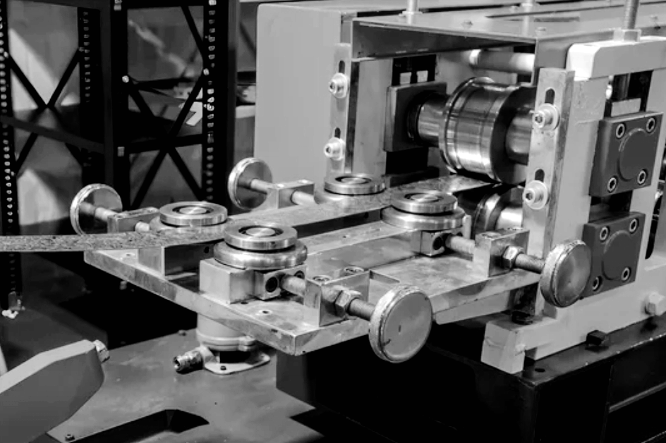
Multi-slide stamping depends on tool timing and clearance. Each slide must reach the workpiece, form the feature, and retract without colliding with another tool or trapping the part. Small geometry changes can affect tool access, especially around hooks, inward tabs, closed loops, narrow slots, and spring arms.
Forming sequence also affects dimensional stability. If a bend changes the location of a later datum, the part may need a locating feature or restrike action. If a spring arm is over-formed, the material must recover to the intended final angle. If the material has coating or plating requirements, the process must consider whether forming occurs before or after surface treatment.
Buyers should identify which dimensions control assembly and which surfaces control electrical contact, spring force, cosmetic appearance, or sliding fit. That information helps the stamping supplier decide how to locate the part, where to accept tool marks, and what inspection evidence should be prepared.
Material and Part Feature Decisions in Multi-Slide Stamping RFQs
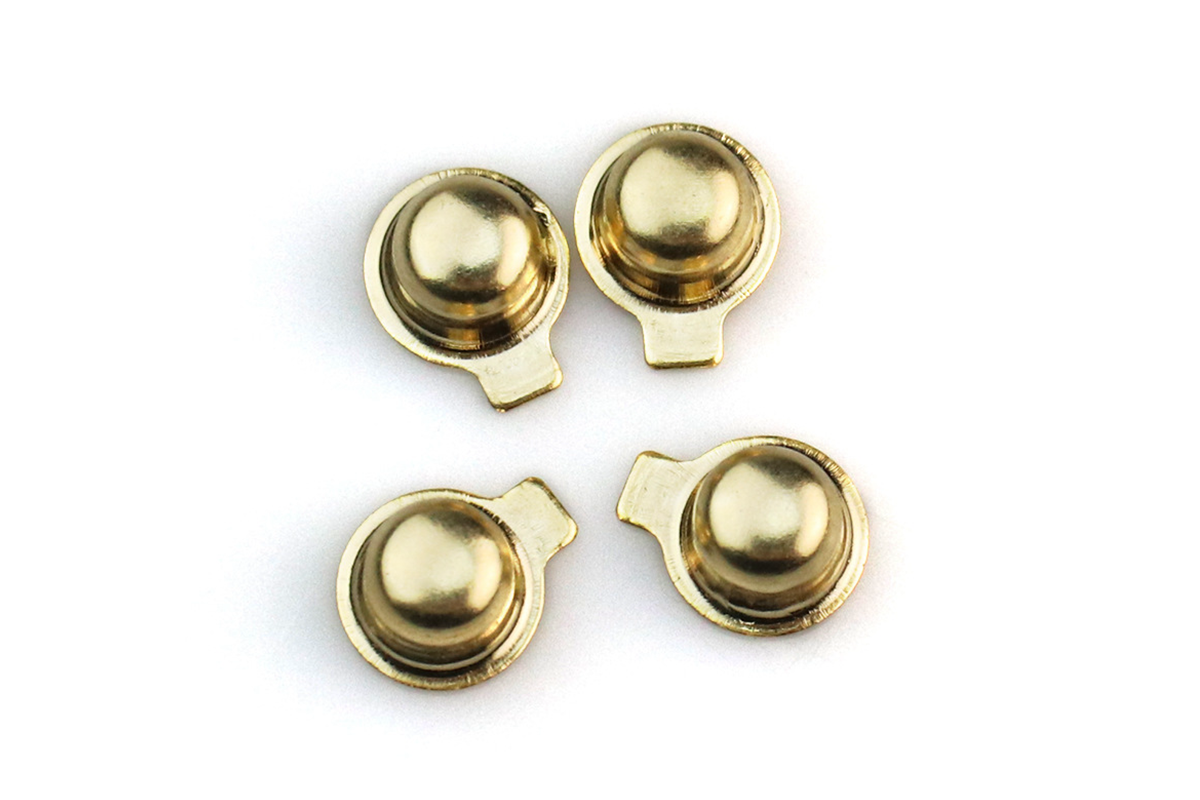
Material choice is important because multi-slide parts often rely on bending response, spring behavior, or electrical performance. Stainless steel, spring steel, carbon steel, brass, copper, phosphor bronze, beryllium copper, and nickel alloys may be considered depending on the application, but material availability, temper, conductivity, corrosion behavior, and forming limits must be reviewed against the drawing.
Part features that deserve early review include bend radius, slot width, tab length, contact tip geometry, narrow arms, hooks, lances, coined areas, plating surfaces, and cutoff burr location. A sharp inside radius in a hard temper can crack. A burr on a mating edge can affect assembly. A plated contact surface may need coating thickness control. A spring clip may need force testing or functional gauging if the buyer specifies those acceptance criteria.
Part Feature | Multi-Slide Stamping Risk | Quotation Impact | Inspection Evidence |
|---|---|---|---|
Spring arm or contact beam | Springback, set, or contact-force variation. | May require material temper review, over-forming, or functional testing. | Functional gauge, force check, or dimensional report. |
Hook, tab, or side bend | Tool access, cracking, and bend sequence interference. | May require revised bend order or local radius adjustment. | Angle inspection, visual check, and assembly fit check. |
Cutoff edge | Burrs, deformation, or sharp edges. | May require deburring, edge orientation control, or packaging protection. | Burr standard, edge visual inspection, or go/no-go gauge. |
Plated contact surface | Tool marks, coating damage, or thickness variation. | May require finishing sequence review and protected handling. | Coating thickness report, conductivity check, or visual standard. |
Multi-Slide Stamping Compared With Progressive, Deep Drawing, and Transfer Dies
Multi-slide stamping should be compared with other stamping routes before tooling release. The best choice depends on part size, number of bend directions, depth, handling method, strip layout, and production stage.
Progressive die stamping may be better for strip-fed parts with many holes, shallow bends, and a station sequence that can fit a progressive die. Multi-slide stamping may be better when compact parts need side actions and bends from multiple directions.
Deep drawn metal stamping may be better when the part is a cup, shell, sleeve, or other hollow shape. Multi-slide stamping focuses on small formed strip parts rather than controlled drawing of sheet metal into a cavity.
Transfer die stamping may be better for larger formed parts that need station-to-station handling. Multi-slide stamping is more often considered when the part is narrow, compact, and suited to slide actions from different sides.
Inspection and Secondary Operations for Multi-Slide Stamped Parts
Inspection should match the part function. A multi-slide stamped part may need checks for bend angle, free height, contact gap, hole position, tab location, burr direction, spring force, flatness, edge condition, coating thickness, conductivity, and visual appearance. Depending on the drawing, inspection evidence may include first article inspection, dimensional reports, optical inspection, go/no-go gauges, force testing, coating thickness reports, conductivity checks, and visual standards.
Secondary operations can be central to part performance. Common post-processing steps include deburring, cleaning, heat treatment, stress relief, plating, passivation, laser marking, riveting, insertion, or assembly. If the part is used as an electrical contact, spring clip, or retaining element, the RFQ should define the final functional condition after all secondary operations, not only the stamped shape.
What Neway Precision Reviews Before Multi-Slide Stamping Production
For a multi-slide stamping review, Neway Precision checks the strip layout, bend sequence, material behavior, side-action access, cutoff method, secondary operations, and inspection scope. A complete RFQ normally includes a 2D drawing, 3D model if available, material grade and temper, sheet thickness, production quantity or stage, critical dimensions, spring-force or contact requirements if applicable, burr-side preference, finishing requirements, packaging needs, and inspection records.
If the design is still changing, a prototype or simplified forming route may be needed before production tooling. Once the geometry, material, and acceptance criteria are stable, multi-slide metal stamping can be evaluated as a production route for compact formed metal parts with multi-directional bend features.
Related FAQs