What Is Transfer Die Stamping And How Does It Work?
Transfer Die Stamping RFQ Decision for Complex Sheet Metal Parts: Transfer die stamping is a sheet metal stamping process that moves a workpiece from one die station to the next so each station can blank, draw, form, pierce, flange, trim, or shape the part in sequence. This article explains how transfer die stamping works, when the route suits larger or more three-dimensional stamped parts, and what RFQ details buyers should define before tooling review.
The practical RFQ problem is part handling. In transfer die stamping, the part is not carried through the tool as one continuous strip in the same way as progressive die stamping. The part must be lifted, transferred, located, and supported between stations. That makes datum design, handling surfaces, transfer-finger clearance, formed geometry, material behavior, and inspection requirements central to the quote.
How Transfer Die Stamping Moves Parts Between Forming Stations
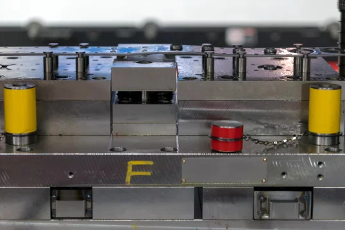
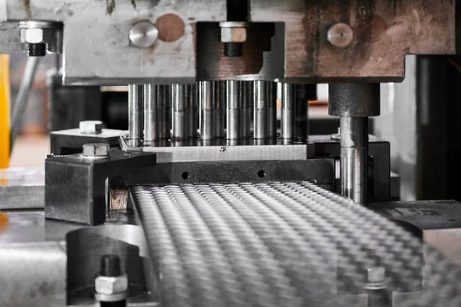
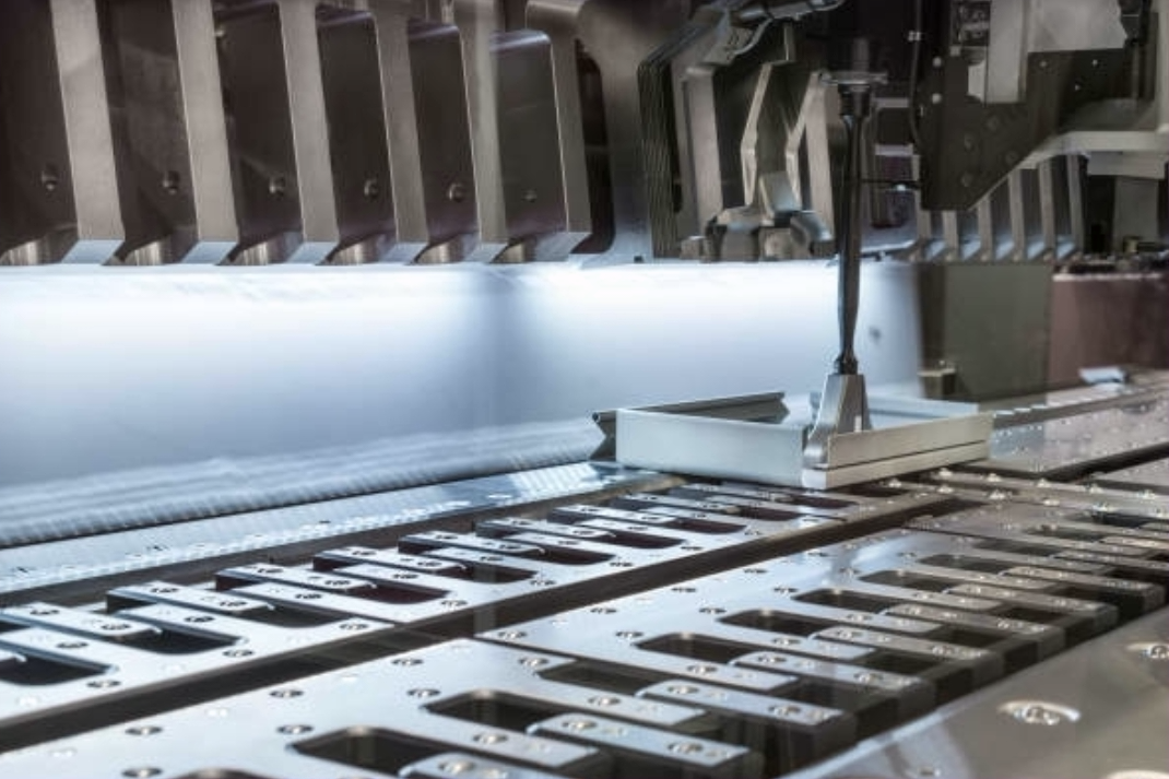
Transfer die stamping uses a sequence of dies arranged in a press line or transfer press. A blank or partially formed workpiece enters the first station, then mechanical transfer fingers or another transfer system moves the workpiece to the next station after each press stroke. Each station performs a defined operation such as blanking, drawing, piercing, trimming, flanging, embossing, bending, or restriking.
The process is useful when the part cannot remain attached to a carrier strip or when the geometry needs more open access than a progressive die can provide. Because the workpiece is separated from the strip early, the tooling can form larger shapes, deeper features, or complex profiles that need room around the part. The trade-off is that the transfer system must hold and locate the part without damaging functional or cosmetic surfaces.
Buyers should not treat transfer handling as a hidden tooling issue. If a surface is cosmetic, sealing, bearing, electrically conductive, or used as an assembly datum, the RFQ should identify that surface. The tooling plan can then avoid using that area as a rough handling surface when possible.
When Transfer Die Stamping Fits Larger or More Three-Dimensional Parts
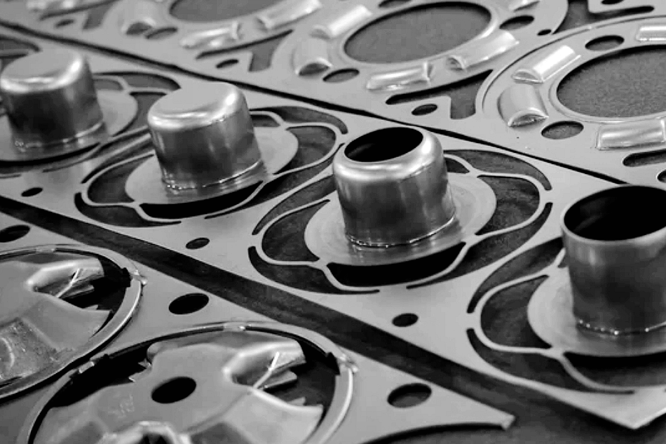
Transfer die stamping may fit larger brackets, drawn shells, covers, frames, trays, structural stampings, mounting plates, and formed housings that need several operations but cannot travel through a progressive strip layout. The route is often considered when a part has depth, flange features, side forms, pierced holes after forming, or geometry that needs open station access.
The process is not automatically better than progressive stamping. For compact parts with many holes and shallow bends, progressive die stamping may offer simpler strip feeding. For cups and shells with dominant depth, deep drawing may be the core route. For small contacts or spring clips with bends from several directions, multi-slide stamping may be more practical. Transfer die stamping becomes attractive when part handling between stations solves a geometry problem that strip-fed tooling cannot solve cleanly.
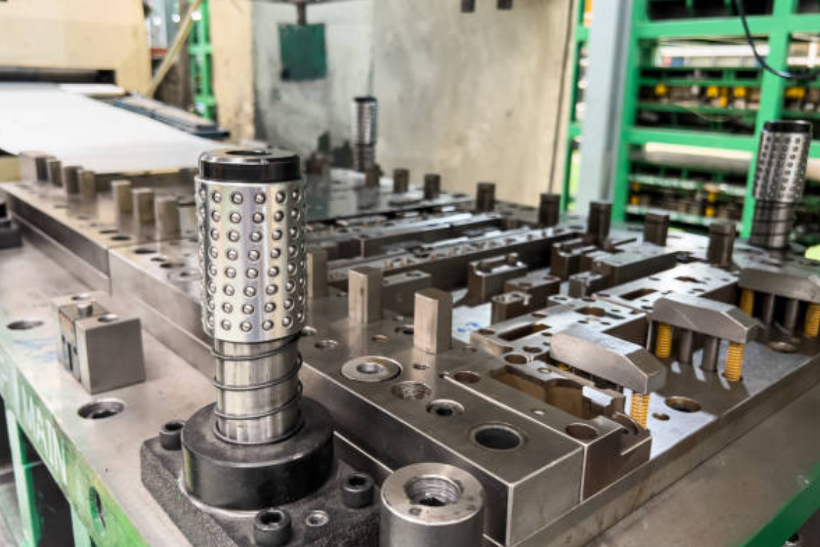
Transfer Die Stamping Workflow From Blank Loading to Part Removal
The workflow begins with a part drawing, material specification, and station plan. Tooling engineers decide whether the part starts as a blank, a coil-fed blank, or a preform. The station sequence then defines how the part is formed, how the transfer system grips the part, and where datums are maintained during each move.
During production, the first station may blank or preform the workpiece. Transfer fingers move the workpiece to the next station, where a new forming or cutting operation occurs. The part may be drawn, restruck, pierced, trimmed, flanged, or coined across several stations. At the end, the finished part is removed for inspection, finishing, packaging, or secondary operations.
Process Stage | What Happens in Transfer Die Stamping | Manufacturing Risk to Control | RFQ Information Needed |
|---|---|---|---|
Part and blank review | The drawing, material grade, sheet thickness, and starting blank are reviewed. | Wrong blank size or material temper can cause splits, wrinkles, or poor fit. | 2D drawing, 3D model, material specification, thickness, and production stage. |
Station sequence planning | Blanking, drawing, forming, piercing, trimming, and restriking are assigned to stations. | Features may interfere if the order does not support material flow or tool access. | Critical features, datum surfaces, assembly interfaces, and cosmetic surfaces. |
Transfer handling | Transfer fingers move the workpiece from one die station to another. | Part drop, mislocation, handling marks, and deformation can occur. | Allowed handling surfaces, surface protection needs, and fragile feature locations. |
Forming and piercing | The part is shaped, pierced, trimmed, flanged, or coined across stations. | Springback, burrs, hole distortion, and surface marks may affect function. | Burr side, hole function, bend requirements, and inspection method. |
Removal and downstream work | The formed part exits for finishing, inspection, packaging, or assembly. | Secondary operations can change dimensions, appearance, or edge condition. | Finishing requirement, packaging standard, traceability, and inspection records. |

Tooling, Transfer Fingers, Datums, and Part Handling Risks
Transfer die stamping depends on reliable part transfer as much as forming force. The transfer fingers must grip or support the workpiece without blocking the next forming operation. The part must arrive at each station in a repeatable position, and the tooling must maintain functional datums while the shape changes.
Handling risks are common when the part has thin flanges, tall walls, soft aluminum, visible surfaces, or fragile formed features. A poorly chosen grip area can leave marks, distort the part, or shift the datum reference. For this reason, buyers should identify appearance surfaces, sealing edges, mating faces, clip features, hole patterns, and areas that cannot tolerate handling marks.
The tooling plan may include pilots, nests, gauges, transfer-finger shapes, part supports, sensors, scrap control, and station-by-station adjustments. The exact tooling solution is subject to drawing review, material behavior, press layout, and acceptance criteria.
Material, Geometry, and Volume Factors in Transfer Die Stamping RFQs
Transfer die stamping can process common sheet metal families such as low-carbon steel, stainless steel, aluminum, brass, copper, and coated sheet, but material behavior strongly affects station sequence. Ductility, temper, work hardening, coating sensitivity, grain direction, and surface side can influence drawing, bending, trimming, and part handling.
Geometry factors include part size, depth, flange width, side-wall shape, hole location, trim edge, bend radius, and formed feature access. Holes that must remain accurate after forming may need to be pierced in a later station. Trim edges may need deburring. Cosmetic panels may need special handling and packaging. Deep or asymmetric forms may need restrike stations to control springback or fit.
Volume matters because transfer tooling requires design, tryout, maintenance, and process control. If the part is still changing, buyers may use prototype routes before transfer tooling. If the design is stable and repeat demand is expected, transfer die stamping can be reviewed for production consistency and reduced manual handling compared with separate forming operations.
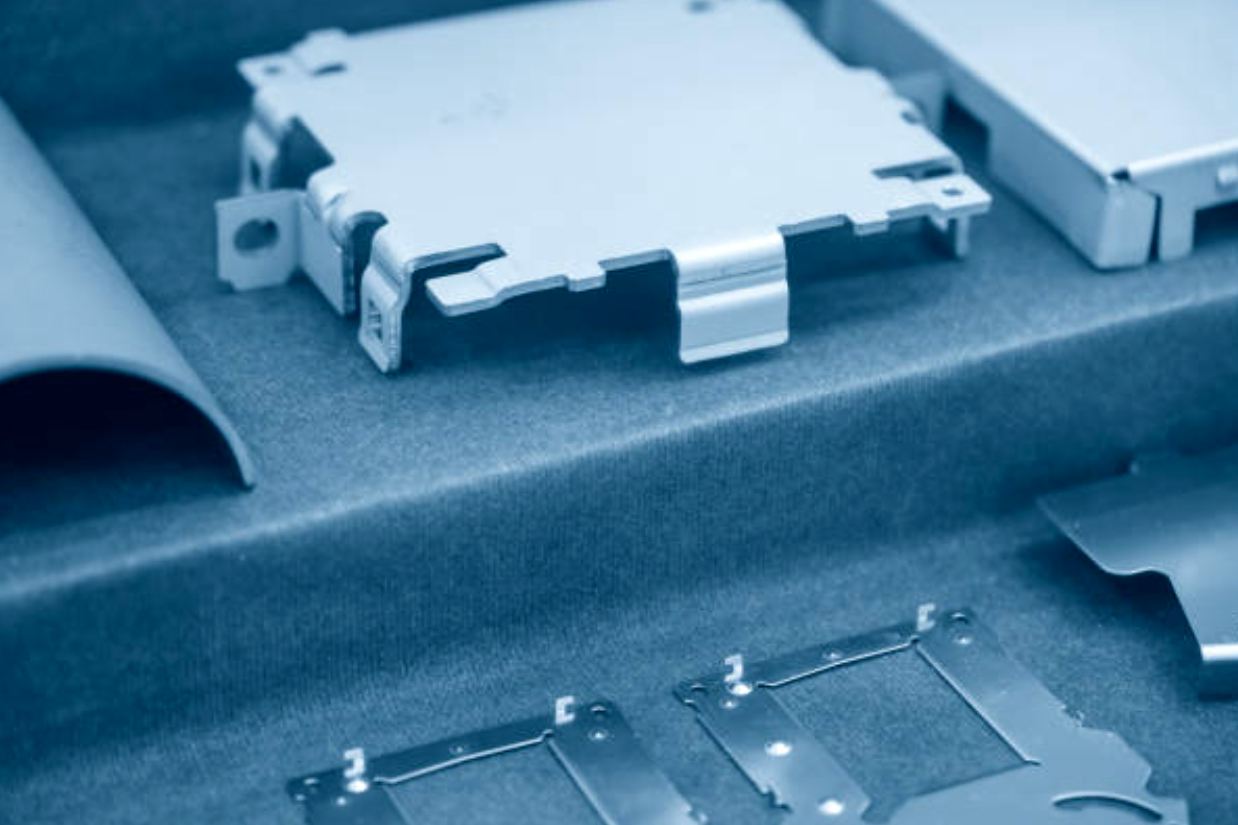
Buyer Decision | Transfer Die Stamping Impact | Manufacturing Risk | Evidence to Request |
|---|---|---|---|
Functional datum selection | Controls how the part is located between stations. | Datum shift can affect hole location and assembly fit. | FAI report, dimensional report, or gauge plan. |
Allowed handling surfaces | Guides transfer-finger and nest design. | Visible marks or deformation may occur on sensitive surfaces. | Visual standard, surface requirement, and packaging review. |
Hole and slot timing | Determines whether features are pierced before or after forming. | Distortion can affect functional holes if timing is wrong. | Optical measurement, go/no-go gauge, or CMM check for selected features. |
Secondary operations | May add deburring, welding, riveting, plating, cleaning, or assembly. | Post-processing can change fit, appearance, or coating condition. | Coating thickness report, visual inspection, or assembly check. |
Transfer Die Stamping Compared With Progressive, Deep Drawing, and Multi-Slide Stamping
The correct stamping route depends on how the part moves through production. Transfer die stamping moves separated workpieces between stations. Progressive die stamping carries the part on a strip. Deep drawing focuses on material flow into a cavity. Multi-slide stamping forms small parts from several directions.
Progressive die stamping may be better when the part can remain connected to a carrier strip and the station sequence is compact. Deep drawn metal stamping may be better when the main requirement is a cup, shell, sleeve, or hollow form. Multi-slide metal stamping may be better for small clips, contacts, and spring-like components with bends from multiple directions.
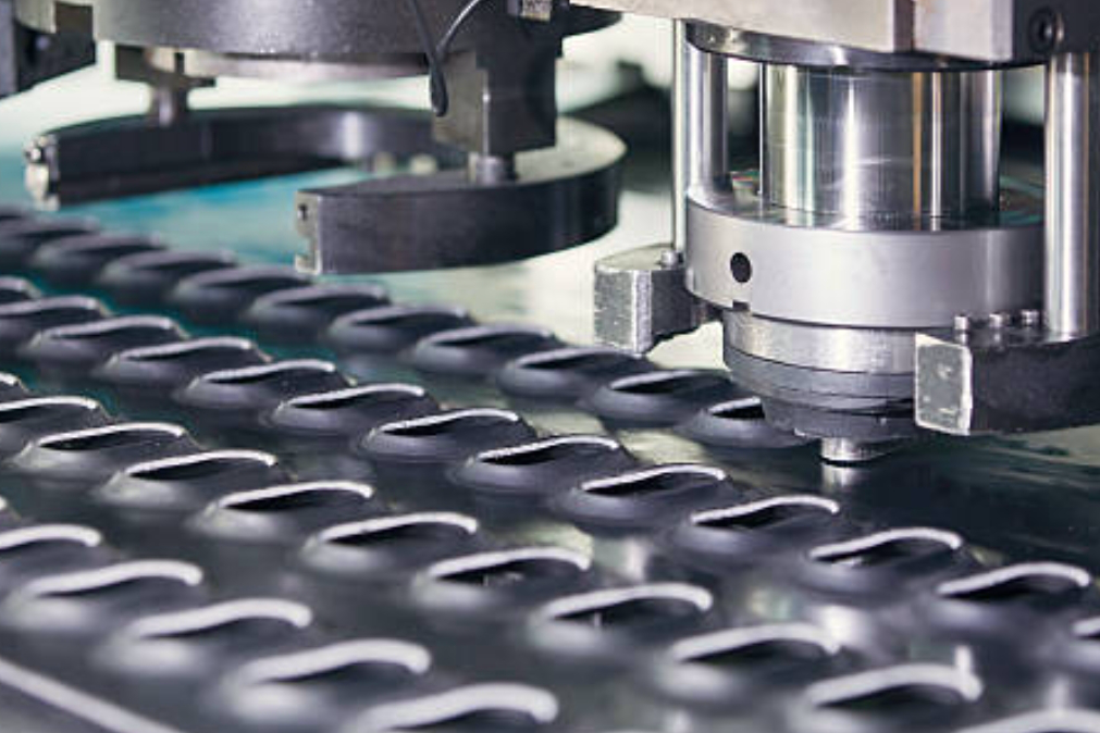
Inspection and Secondary Operations for Transfer-Stamped Parts
Inspection should match the part function and station risks. A transfer-stamped part may need checks for hole location, flange height, bend angle, outside profile, depth, flatness, trim edge, burr condition, surface marks, and assembly fit. Depending on the drawing, inspection evidence may include first article inspection, dimensional reports, optical inspection, CMM checks for selected datums, go/no-go gauges, coating thickness reports, hardness checks after heat treatment, and visual standards.
Secondary operations should be included in the RFQ because they may affect dimensions and appearance. Transfer-stamped parts may need deburring, tapping, clinching, riveting, welding, cleaning, plating, passivation, anodizing, heat treatment, laser marking, assembly, or packaging protection. If the final part must meet a buyer-specific acceptance standard, that standard should be provided before quotation.
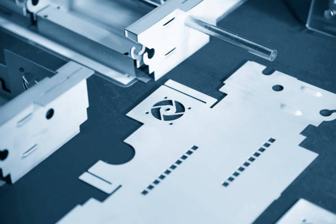
What Neway Precision Reviews Before Transfer Die Production
For a transfer die stamping review, Neway Precision checks part geometry, material behavior, station sequence, handling surfaces, secondary operations, and inspection scope. A complete RFQ normally includes a 2D drawing, 3D model if available, material grade and temper, sheet thickness, expected production stage, annual demand or order pattern, functional datums, cosmetic surfaces, burr-side preference, finishing requirements, packaging needs, and inspection records.
If the part is still being developed, a prototype or pilot route may be used before transfer tooling. Once the geometry and acceptance criteria are stable, transfer die stamping can be evaluated for repeatable production of complex sheet metal parts that need controlled movement between forming stations.
Related FAQs