13 Mechanical Design Considerations for Metal Stamping Parts
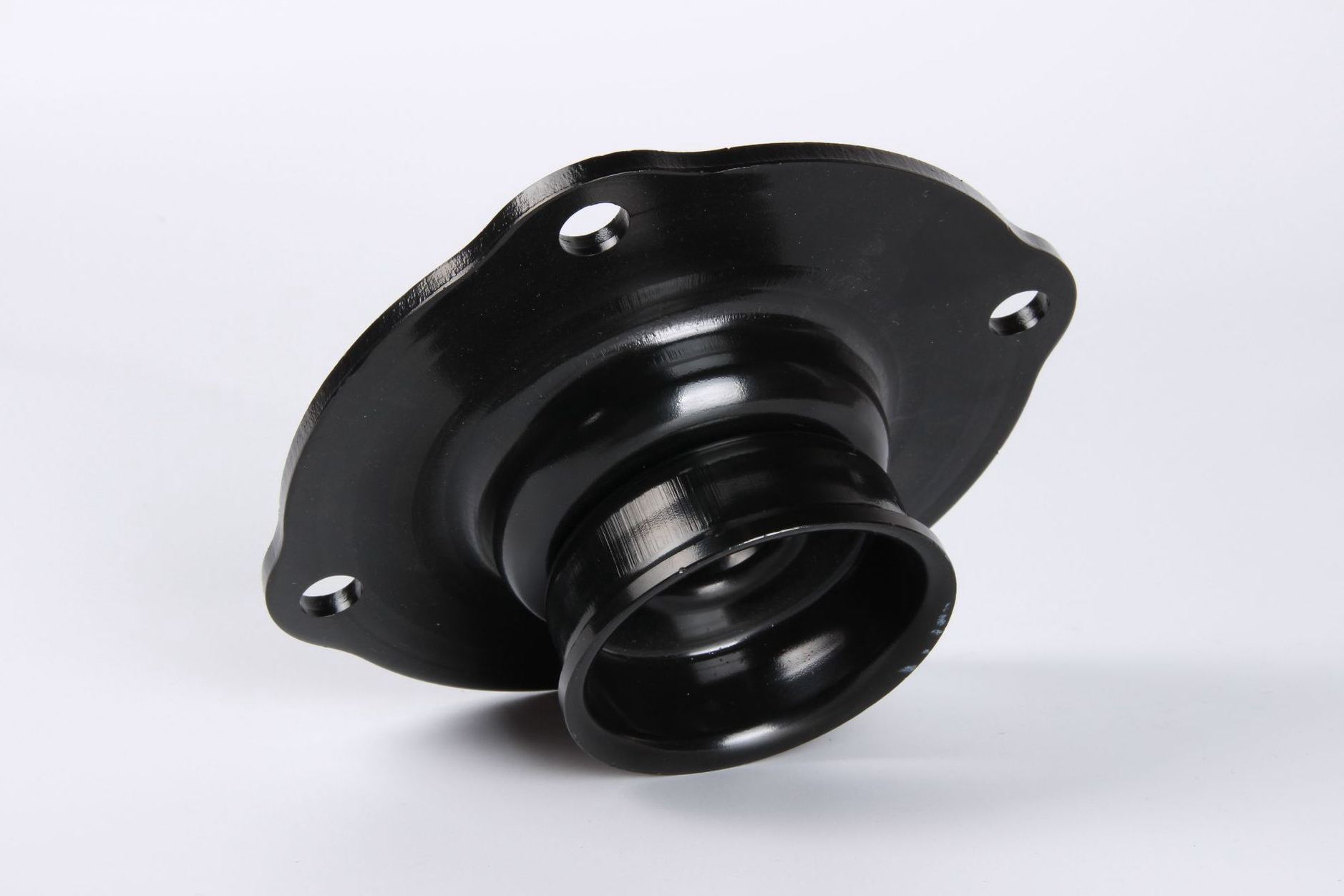
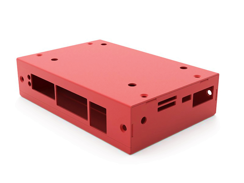
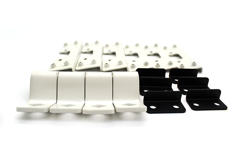
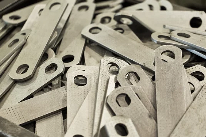
Mechanical design for metal stamping parts should be reviewed before tooling because the stamping die, punch, material strip, forming sequence, and inspection plan are all affected by part geometry. The process is sheet metal stamping for parts such as clips, brackets, terminals, shields, covers, washers, springs, tabs, and formed sheet metal components. The practical RFQ problem is checking whether material selection, thickness, bend radius, hole spacing, web width, burr direction, formed features, tolerances, and secondary operations are suitable before die design begins.
What are the 13 key design considerations for metal stamping parts?
The 13 key considerations are material grade, sheet thickness, grain direction, bend radius, draw radius, hole size, hole-to-edge distance, slot and web width, burr direction, formed features, datum and tolerance scheme, insert or hardware allowance, and post-processing requirement. These items should be reviewed together because changing one feature can affect tooling, strip layout, part strength, and cost.
Design Consideration | Why It Matters | RFQ Question |
|---|---|---|
Material grade | Controls ductility, strength, springback, corrosion resistance, and tool wear. | Is the exact alloy or approved alternate material defined? |
Sheet thickness | Affects tonnage, bend radius, hole quality, and strip layout. | Is thickness tolerance important for fit or forming? |
Grain direction | Can affect bending, cracking, and spring behavior. | Does the part require a controlled grain direction? |
Bend radius | Controls cracking, thinning, springback, and tooling selection. | Is the inside radius manufacturable for the material? |
Draw radius | Affects material flow in cups, shells, ribs, and drawn forms. | Is the draw depth realistic for the material and thickness? |
Hole size | Small holes increase punch breakage and burr risk. | Are critical holes stamped, drilled, or finished later? |
Hole-to-edge distance | Short distances can distort edges or weaken webs. | Can holes move away from bends, edges, or narrow tabs? |
Slot and web width | Narrow webs can tear, distort, or create tooling weakness. | Are slot widths and bridges compatible with die strength? |
Burr direction | Burrs affect assembly, contacts, coating, and handling safety. | Which side should control burr direction and deburring? |
Formed features | Louvers, embosses, ribs, and offsets need station planning. | Which formed features are functional and which are cosmetic? |
Datum and tolerances | Unclear datums make inspection and tool correction difficult. | Which dimensions are critical to fit or function? |
Inserts and hardware | Hardware changes hole size, access, and assembly sequence. | Are inserts, rivets, fasteners, or threads included? |
Post-processing | Plating, coating, heat treatment, and cleaning can change requirements. | What finishing and cleanliness requirements follow stamping? |
How should material and thickness be selected for stamping?
Material and thickness should be selected by function first, then checked for stampability. Carbon steel, stainless steel, aluminum, copper alloys, brass, and spring materials can all be stamped in suitable conditions, but each material changes springback, burr formation, formability, tool wear, and surface finish risk.
Buyers should define the material grade, temper, coating, thickness tolerance, and any approved substitutions. If the part needs spring force, electrical conductivity, corrosion resistance, cosmetic finish, or high strength, those requirements should be stated before tooling design.
How do holes, slots, and webs affect stamping design?
Holes, slots, and webs affect punch strength, die clearance, burr direction, and strip stability. Very small holes, narrow bridges, and slots near edges can increase punch wear, slug pulling, cracking, and distortion.
The RFQ should identify functional holes, clearance holes, decorative openings, and holes that may be finished after stamping. If a hole controls assembly alignment, the buyer should define datum references and inspection method rather than relying only on a general profile tolerance.
How do bends, draws, and formed features change the stamping route?
Bends, draws, ribs, louvers, embosses, offsets, and tabs change the stamping route because each formed feature may need a dedicated die station or a specific sequence. Forming too close to a hole or cut edge can cause distortion, cracks, or dimensional shift.
Buyers should define inside bend radius, draw depth, louver direction, emboss height, and cosmetic side. For formed features that interact with mating parts, the drawing should identify the inspection datum and acceptance method.
Why are tolerances, datums, and burr direction important?
Tolerances, datums, and burr direction determine how the stamped part will be inspected and assembled. A stamped part may have many noncritical features, but only a few holes, tabs, or bends may control function. Marking those features prevents unnecessary tooling cost while protecting assembly performance.
Burr direction matters for electrical contacts, sealing surfaces, coated parts, sliding parts, and handled edges. Buyers should specify burr-sensitive surfaces and whether deburring, tumbling, brushing, plating preparation, or edge breaking is required.
How do tooling and production volume affect stamping design?
Tooling and production volume affect whether simple tooling, compound tooling, progressive stamping, or transfer stamping should be reviewed. A low-volume prototype may start with laser cutting and forming, while a stable high-volume part may justify progressive tooling.
Design changes after tooling begins can be expensive. Buyers should confirm part function, material, key dimensions, and annual volume before approving die design. If the design is still changing, the RFQ should identify which features are experimental and which features are production intent.
What secondary operations should be planned with stamped parts?
Stamped parts may need tapping, threading, welding, riveting, insert installation, heat treatment, deburring, cleaning, passivation, plating, anodizing, powder coating, or assembly. These operations can affect hole size, burr direction, surface finish, and inspection requirements.
Planning secondary operations before tooling helps avoid access problems and rework. For example, a plated electrical terminal needs surface and burr control, while a bracket with press-fit hardware needs hole size and material thickness control.
What should buyers send for a metal stamping design review?
Buyers should send the CAD file, dimensioned drawing, material grade, thickness, annual volume, batch quantity, critical dimensions, burr direction, surface finish, formed feature notes, hardware requirements, coating or plating requirements, and assembly context. A marked-up drawing that identifies functional features helps the supplier focus DFM feedback.
The best design review confirms manufacturability before tooling money is committed. It should answer whether the part can be stamped as drawn, which features need adjustment, which tolerances drive cost, and which inspection method protects the buyer's assembly.
Related FAQs
What is progressive stamping and how does it benefit high-volume production?
Which materials are most cost-effective for high-volume metal stamping?
What are the common issues encountered during mass production metal stamping?
Why is regular tooling maintenance critical in high-volume metal stamping processes?