Mastering Sheet Metal Fabrication: Process integration of Sheet Metal Stamping
Sheet Metal Fabrication Integration RFQ Decision for Stamped and Joined Parts: Sheet metal fabrication often combines laser cutting, stamping, bending, flanging, riveting, rivetless clinching, resistance spot welding, screw fastening, surface finishing, and inspection to turn flat sheet into functional metal assemblies. This article explains how sheet metal stamping fits into a broader fabrication route and what RFQ details buyers should define before ordering custom brackets, covers, enclosures, panels, clips, and joined sheet metal parts.
The practical RFQ problem is process sequence. A stamped feature may need to be created before bending, a hole may need to be pierced before riveting, a flange may need clearance for welding, and a surface finish may need protection during assembly. Buyers should define material grade, sheet thickness, part function, joint type, burr direction, cosmetic surfaces, finishing requirements, assembly loads, and inspection records before quotation.
How Sheet Metal Fabrication Combines Cutting, Stamping, Bending, and Joining
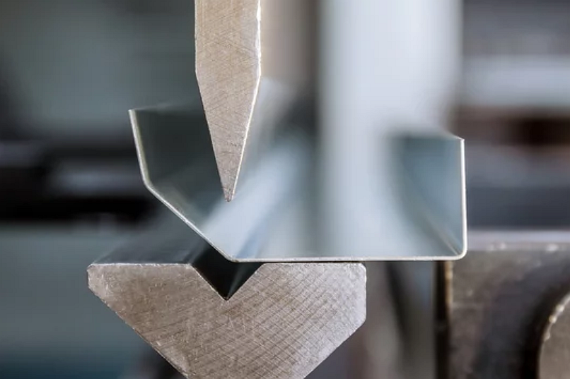
Sheet metal fabrication is a route, not a single operation. A fabricated part may start as a laser-cut blank, move to stamping for pierced holes or formed features, pass through bending for flanges, and then use riveting, clinching, welding, or screw fastening to create an assembly. The final part may also need deburring, cleaning, powder coating, plating, anodizing, passivation, marking, or packaging protection.
Stamping becomes important when repeated features, holes, louvers, embosses, tabs, or formed shapes need a controlled production route. Laser cutting may support prototypes or low-volume flat profiles. Bending creates angles, channels, and enclosure walls. Joining methods then connect sheets, inserts, brackets, reinforcements, or mating hardware. The sequence must protect datums, hole positions, surface finish, and assembly fit.
A strong fabrication RFQ should describe the finished assembly, not only each individual operation. If a bend changes hole location, a rivet deforms a flange, or welding heat affects flatness, the process route needs to be reviewed as one manufacturing plan.
When Sheet Metal Stamping Should Be Integrated With Laser Cutting or Bending
Sheet metal stamping should be integrated with laser cutting or bending when the part needs both production repeatability and flexible geometry. A new bracket may be laser cut and bent during prototype review, then changed to stamped blanks when the design stabilizes. A cover may use stamping for louvers and holes, bending for flanges, and riveting for internal hardware. A panel may need laser-cut revisions during development before a stamping tool is justified.
The buyer decision depends on part quantity, revision risk, material thickness, feature complexity, tooling cost, finishing needs, and inspection scope. When the design is still changing, laser cutting and bending may reduce upfront tooling commitment. When demand is stable and repeated features drive cost or consistency, stamping may become the better production route.
Fabrication Stage | Typical Process Role | Integration Risk | RFQ Information Needed |
|---|---|---|---|
Laser cutting or blanking | Creates the flat profile, holes, slots, and initial blank shape. | Heat distortion, burrs, edge quality, or revision changes can affect later steps. | Material grade, thickness, flat profile, hole function, and prototype quantity. |
Sheet metal stamping | Adds repeatable pierced, blanked, embossed, louvered, or formed features. | Die sequence can affect datums, burr side, and feature distortion. | Critical dimensions, burr direction, production demand, and inspection plan. |
Metal bending | Forms flanges, angles, channels, brackets, and enclosure walls. | Springback, bend radius, hole distortion, and bend collision may occur. | Bend angle, inside radius, grain direction, datum surfaces, and cosmetic side. |
Joining and assembly | Connects sheet parts using rivets, clinches, spot welds, screws, or inserts. | Joint deformation, heat input, fastener access, or serviceability limits can affect function. | Joint load, access direction, fastener type, assembly sequence, and acceptance criteria. |
Finishing and inspection | Controls appearance, corrosion behavior, coating, markings, and final acceptance. | Finishing can change dimensions, cover threads, damage joints, or expose burrs. | Finish specification, masking, coating thickness, packaging, and inspection records. |
Flanging and Riveting for Stamped Sheet Metal Assemblies
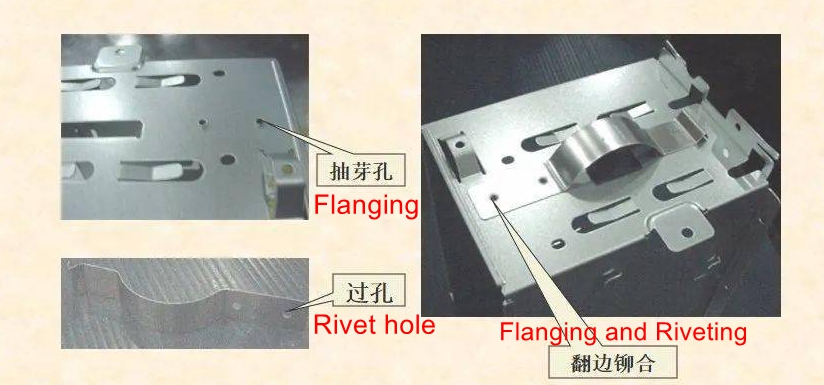
Flanging and riveting are often used when a sheet metal part needs a mechanical joint without relying on a welded seam. A flange can provide overlap, stiffness, alignment, or a surface for rivets. Riveting can attach brackets, covers, hinges, reinforcements, nameplates, or inserts when the joint must be visible, inspectable, or compatible with dissimilar materials.
The RFQ should define flange height, hole location, rivet type, access direction, cosmetic side, joint load, and any service requirement. If the rivet area is close to a bend or stamped feature, the sequence must prevent hole distortion and flange deformation. Inspection may include rivet height, pull-out or torque requirements if specified by the buyer, visual inspection, and assembly fit checks.
Rivetless Clinching for Sheet Metal Joints Without Separate Fasteners
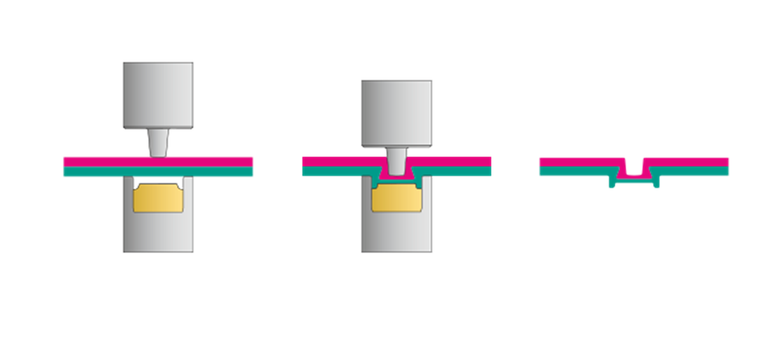
Rivetless clinching, including BTM-type joint concepts, forms a mechanical interlock between sheet layers without adding a separate rivet. The process can be useful when access, cost, appearance, or part count makes separate fasteners less attractive. Clinching requires compatible sheet materials, thickness combinations, overlap area, and tool access from both sides of the joint.
The main risks are joint strength, local deformation, coating damage, and access clearance. Buyers should specify the joint function, load direction, visible surface, acceptable local mark, material stack, coating condition, and any required testing. Clinched joints may not replace welding, riveting, or screws in every assembly, so the route should be selected against the part function and acceptance criteria.
Riveting Process Controls for Fabricated Sheet Metal Parts
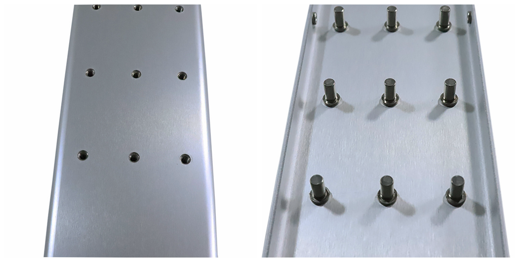
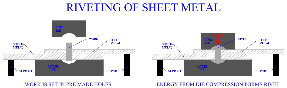
Riveting is a mechanical joining process that depends on hole preparation, fastener choice, tool access, and stack-up control. A stamped or laser-cut hole must align with the mating part. The rivet must fit the material stack. The setting operation must form the joint without crushing thin sheet, damaging a coating, or distorting a nearby bend.
For RFQ review, buyers should define rivet material, joint stack, hole size requirement, visible side, serviceability requirement, corrosion concerns, and whether the joint needs pull-out, shear, torque, vibration, or visual acceptance criteria. If the joint is part of a finished enclosure or cover, the finishing sequence should also be defined before quotation.
Resistance Spot Welding for Sheet Metal Assemblies
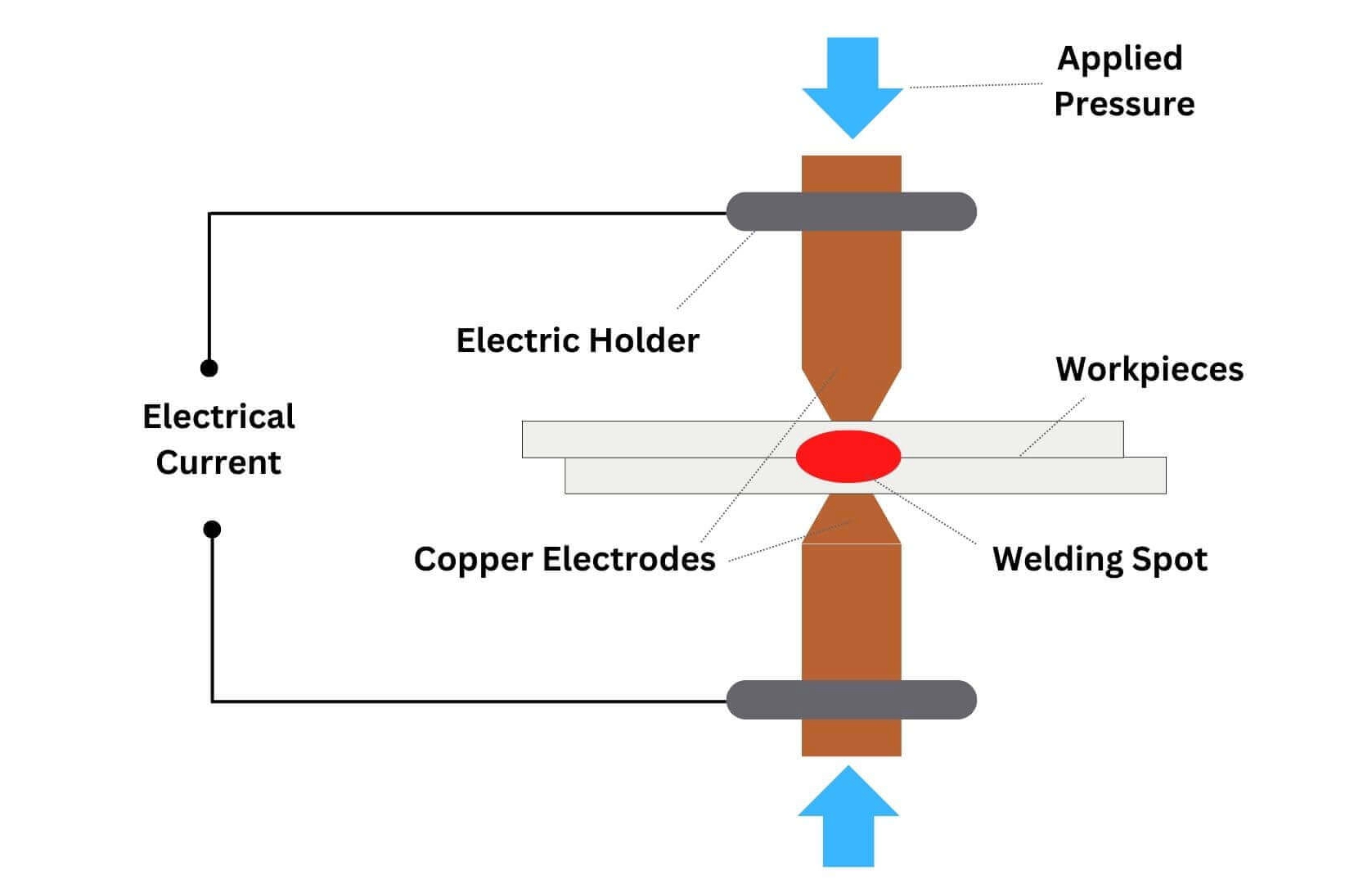
Resistance spot welding joins overlapping sheet metal by applying pressure and electrical current at the weld location. The process may be considered for compatible sheet materials and overlap joints where a localized weld nugget can meet the assembly requirement. Spot welding can reduce separate fasteners, but it also introduces heat, electrode marks, access constraints, and potential distortion.
The RFQ should define material stack, coating condition, weld access, visible surfaces, required weld locations, joint load direction, corrosion protection, and inspection expectations. Inspection may include visual checks, weld location verification, peel or pull testing if specified, and dimensional checks after welding. The final validation remains subject to buyer acceptance criteria.
Screw Connections for Serviceable Sheet Metal Parts
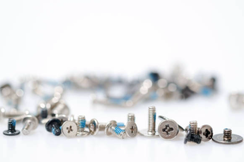
Screw connections are useful when the assembly must be removable, adjustable, or serviceable. Screws may be used with tapped holes, captive nuts, threaded inserts, PEM-style hardware, or mating components depending on sheet thickness and load. The design should allow tool access, prevent thread stripping, and avoid interference with bends, stamped features, or finishes.
Buyers should define screw size, thread type, torque requirement if applicable, access direction, service frequency, corrosion environment, and whether thread locking, washers, inserts, or grounding continuity are needed. Inspection may include thread checks, torque checks, assembly fit, and visual review for surface damage.
RFQ and Inspection Details for Sheet Metal Fabrication Integration
A sheet metal fabrication RFQ should connect every process step to the final part function. Useful information includes the 2D drawing, 3D model if available, material grade, sheet thickness, production stage, expected demand, cutting method, stamping features, bend requirements, joining method, surface finish, assembly function, packaging requirement, and inspection records.
Inspection evidence may include first article inspection, dimensional reports, optical checks, CMM checks for selected datums, go/no-go gauges, rivet or screw checks, weld location verification, coating thickness reports, surface appearance standards, and final assembly fit checks. The right evidence depends on the drawing and buyer acceptance criteria, not on a generic checklist.
What Neway Precision Reviews Before Integrated Sheet Metal Production
For integrated sheet metal fabrication, Neway Precision reviews the process route from blank to finished assembly. The review covers cutting, stamping, bending, joining, finishing, packaging, and inspection. If the design is still changing, prototype routes may use laser cutting and bending before stamping tooling or joining fixtures are finalized. When the design is stable, the full route can be reviewed for repeatability, cost drivers, and acceptance evidence.
Related FAQs