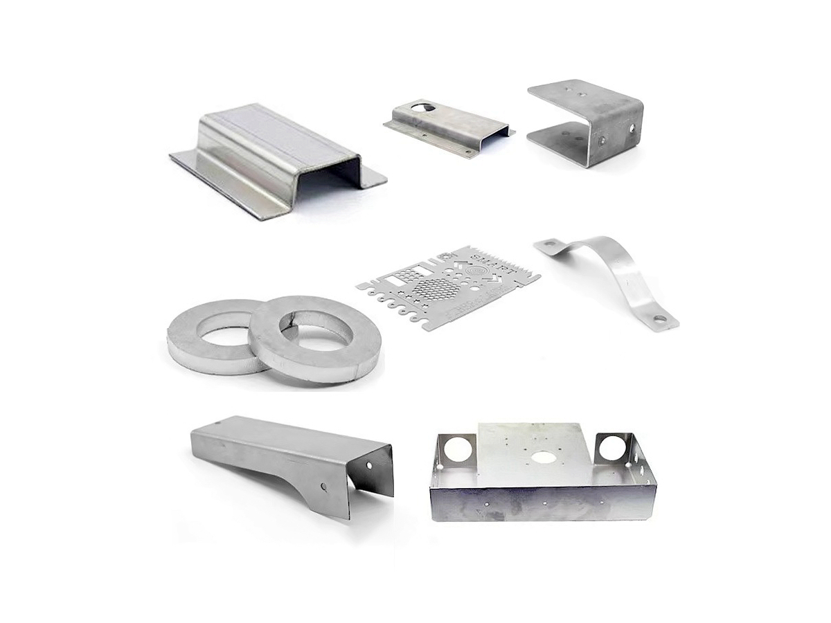
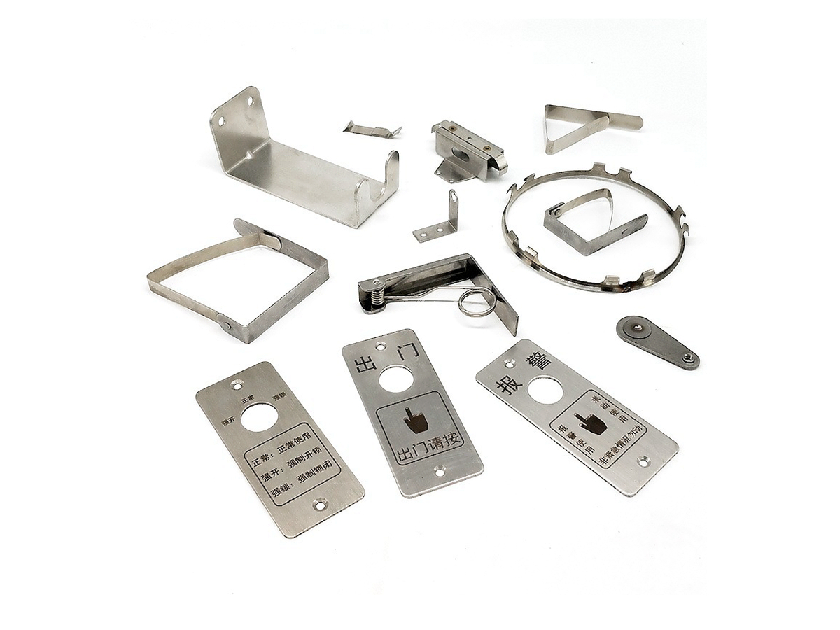
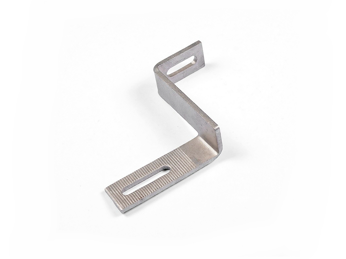
What is Sheet Metal Bending Service?
Sheet metal bending service forms cut sheet metal blanks into angled or curved parts using controlled deformation, commonly with press brake tooling. The process is used after laser cutting, plasma cutting, punching, or shearing to make brackets, panels, enclosures, covers, ducts, guards, mounts, and formed sheet metal components. The practical RFQ problem is defining material grade, sheet thickness, bend radius, bend angle, bend direction, tolerance, hole-to-bend distance, and downstream operations before quotation.
What does sheet metal bending service do?
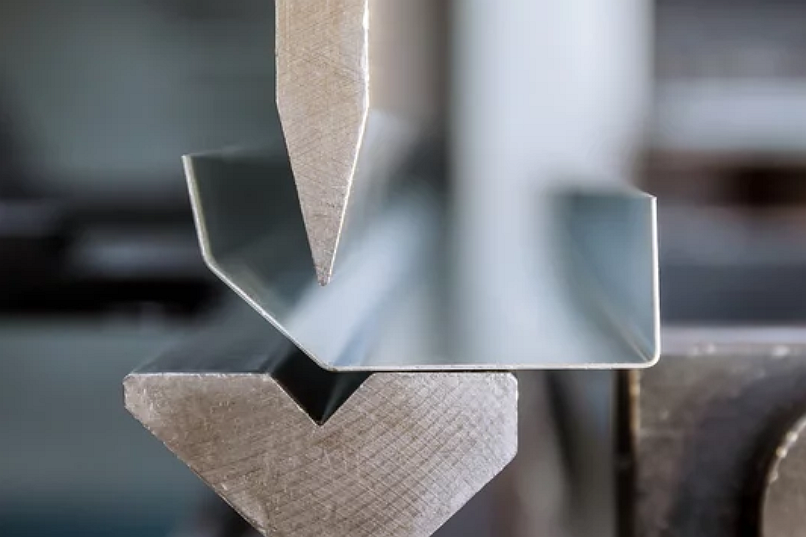
Sheet metal bending changes a flat metal blank into a controlled 3D shape without removing material from the bend line. A punch and die, folding tool, roll bending machine, or forming fixture applies force so the metal yields and keeps the required angle or radius.
The buyer value is that one flat blank can become a functional bracket, enclosure wall, chassis, duct section, cover, support, or mounting plate. Bending can reduce welded joints and assembled pieces, but the final accuracy depends on material behavior, tooling selection, machine setup, and inspection method.
Which sheet metal bending methods are common?
Press brake bending is the most common method for custom sheet metal parts because it supports many angles, flanges, tabs, and box-style forms. Folding is often reviewed for panels, covers, and long flanges where surface marking and part handling matter. Roll bending is used for larger radius curves, cylinders, and curved panels.
Bending Method | Best Fit | RFQ Detail to Define |
|---|---|---|
Press brake bending | Brackets, flanges, enclosures, panels, and formed sheet metal parts. | Bend angle, inside radius, material thickness, tooling access, and tolerance. |
Folding | Long panels, covers, boxes, and visible sheet surfaces. | Flange length, cosmetic side, edge condition, and bend sequence. |
Roll bending | Large-radius curves, cylindrical sections, guards, and architectural panels. | Radius, arc length, material springback, and surface finish requirement. |
Secondary forming | Embosses, offsets, louvers, ribs, and local features. | Feature location, tooling feasibility, and part distortion risk. |
Which materials are commonly used for sheet metal bending?
Carbon steel, stainless steel, aluminum, galvanized steel, copper, and brass are common sheet metal bending materials. Each material has different ductility, springback, crack risk, surface marking risk, and corrosion or finishing requirement.
Stainless steel often needs attention to springback and surface protection. Aluminum can be lightweight and formable, but alloy and temper affect crack risk. Carbon steel is widely used for brackets, housings, and structural panels. Galvanized steel needs coating damage review along the bend. Copper and brass may be chosen for conductivity or decorative appearance but should be reviewed for surface finish and bend marks.
How do bend radius and sheet thickness affect the RFQ?
Bend radius and sheet thickness affect cracking, springback, inside radius, outside dimensions, and tooling choice. A sharp bend on a thick or less ductile material can create cracking or excessive thinning. A larger inside radius may be safer for the material but can change part fit and flange location.
Buyers should avoid assuming one minimum bend radius applies to every material. The RFQ should state material grade, thickness, grain direction if relevant, inside bend radius, bend angle, and whether dimensions are measured to the inside, outside, or neutral position. This information helps the supplier review the flat pattern and the formed part size.
What tolerances and inspection details matter for bent sheet metal parts?
Bent sheet metal parts need tolerance review for bend angle, flange length, hole position after bending, overall height, flatness, and assembly fit. A flat laser cut blank may meet its profile dimensions, but bending can shift hole locations, change flange position, and introduce angular variation.
Inspection Item | Why It Matters | Buyer RFQ Note |
|---|---|---|
Bend angle | Controls fit, enclosure closure, and bracket alignment. | Define angle tolerance and whether functional gauges are needed. |
Flange length | Affects mounting, overlap, and hardware clearance. | State critical flange dimensions and datum references. |
Hole-to-bend distance | Holes too near bends may distort or move after forming. | Mark functional holes and allow DFM review. |
Flatness | Large panels can warp during cutting, bending, or welding. | Define flatness only where it affects assembly or sealing. |
Surface condition | Tool marks or coating damage may affect visible parts. | Identify cosmetic side and finish requirement. |
What secondary operations are often combined with metal bending?
Metal bending is commonly combined with laser cutting, plasma cutting, punching, tapping, countersinking, welding, riveting, grinding, brushing, powder coating, anodizing, plating, passivation, and assembly. These steps should be reviewed together because a bend can affect hole access, welding sequence, coating coverage, and final inspection.
If the part is an enclosure, the RFQ should define cover fit, tab locations, fastening method, hinge or insert requirements, and finish side. If the part is a structural bracket, the RFQ should define load direction, critical holes, bend radius, and whether welds or machined datums are needed after bending.
What design risks should buyers check before ordering bent parts?
The main design risks are springback, cracking, insufficient flange length, holes too close to bend lines, interference between bends, tooling access limits, and cosmetic marking. These risks can be reduced when the supplier reviews the flat pattern, bend sequence, material direction, and critical dimensions before production.
Buyers should send both a flat DXF and a dimensioned formed-part drawing when possible. A 3D model helps communicate final shape, but the 2D drawing should still define bend lines, angles, radii, material, thickness, and inspection requirements.
What should buyers send for a sheet metal bending RFQ?
Buyers should send the CAD file, flat pattern if available, formed-part drawing, material grade, thickness, bend radius, bend angle, grain direction if relevant, cosmetic side, quantity, tolerance notes, downstream operations, and inspection requirement. For repeat production, buyers should also identify critical dimensions that must stay consistent across batches.
A clear sheet metal bending RFQ lets the supplier choose the correct bending method, tooling, bend sequence, and inspection approach. This reduces trial-and-error risk and helps quote the complete route from cutting to forming, finishing, and assembly.
Related FAQs