What is sheet metal fabrication used for? Features, applications and examples?
What is sheet metal fabrication used for?
Sheet metal fabrication is used to make custom metal enclosures, brackets, panels, covers, chassis, guards, trays, frames, and assemblies from flat sheet. The practical RFQ problem is deciding whether a sheet metal route can meet the part's material, thickness, bend geometry, strength, cosmetic surface, hardware, finish, and inspection requirements.
Sheet metal fabrication is often selected when a part can be made by cutting a flat blank and then bending, forming, welding, fastening, finishing, or assembling the sheet into a functional component. The route can be practical for prototypes, pilot lots, and production parts when the design fits sheet thickness, bend radius, and joining requirements.
Which part features fit sheet metal fabrication?
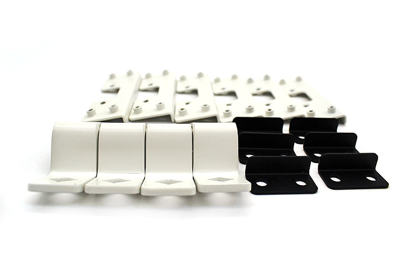
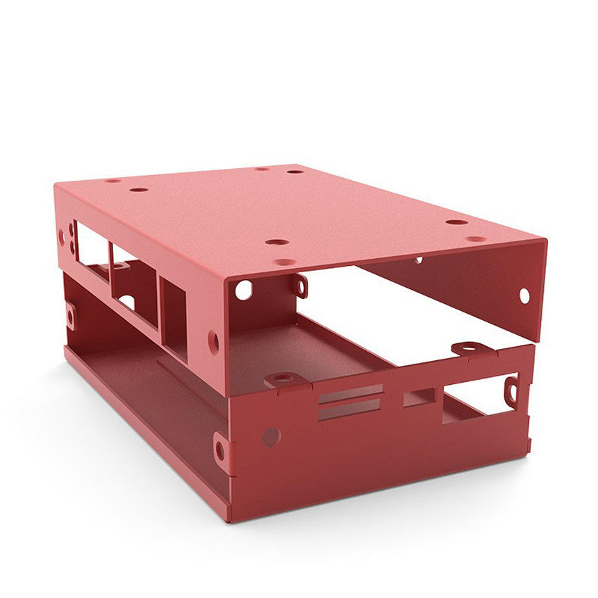
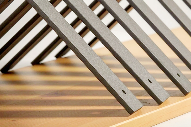
Sheet metal fabrication fits parts with flat faces, flanges, bends, tabs, slots, holes, louvers, ribs, formed features, weld joints, fasteners, or assembled panels. Common examples include electrical enclosures, machine guards, mounting brackets, access panels, sheet metal boxes, covers, chassis parts, racks, and support frames.
The design should account for bend radius, flange length, hole distance from bends, grain direction when relevant, burr direction, weld access, coating thickness, and assembly clearance. Features that ignore these limits can create cracking, springback, hole deformation, warpage, or assembly mismatch.
Which industries use sheet metal fabricated parts?
Sheet metal fabricated parts are commonly reviewed for electronics, industrial equipment, appliances, construction hardware, transportation components, energy equipment, fixtures, cabinets, and general machinery. The industry name does not decide the process; the drawing and functional requirements decide whether sheet metal fabrication is suitable.
For automotive, aerospace, medical, energy, defense, or other regulated applications, the buyer should define qualification requirements, material traceability, inspection records, and acceptance criteria before quotation. A supplier can support manufacturing and inspection evidence, but final validation remains the buyer's responsibility.
How do cutting, bending, and stamping support sheet metal applications?
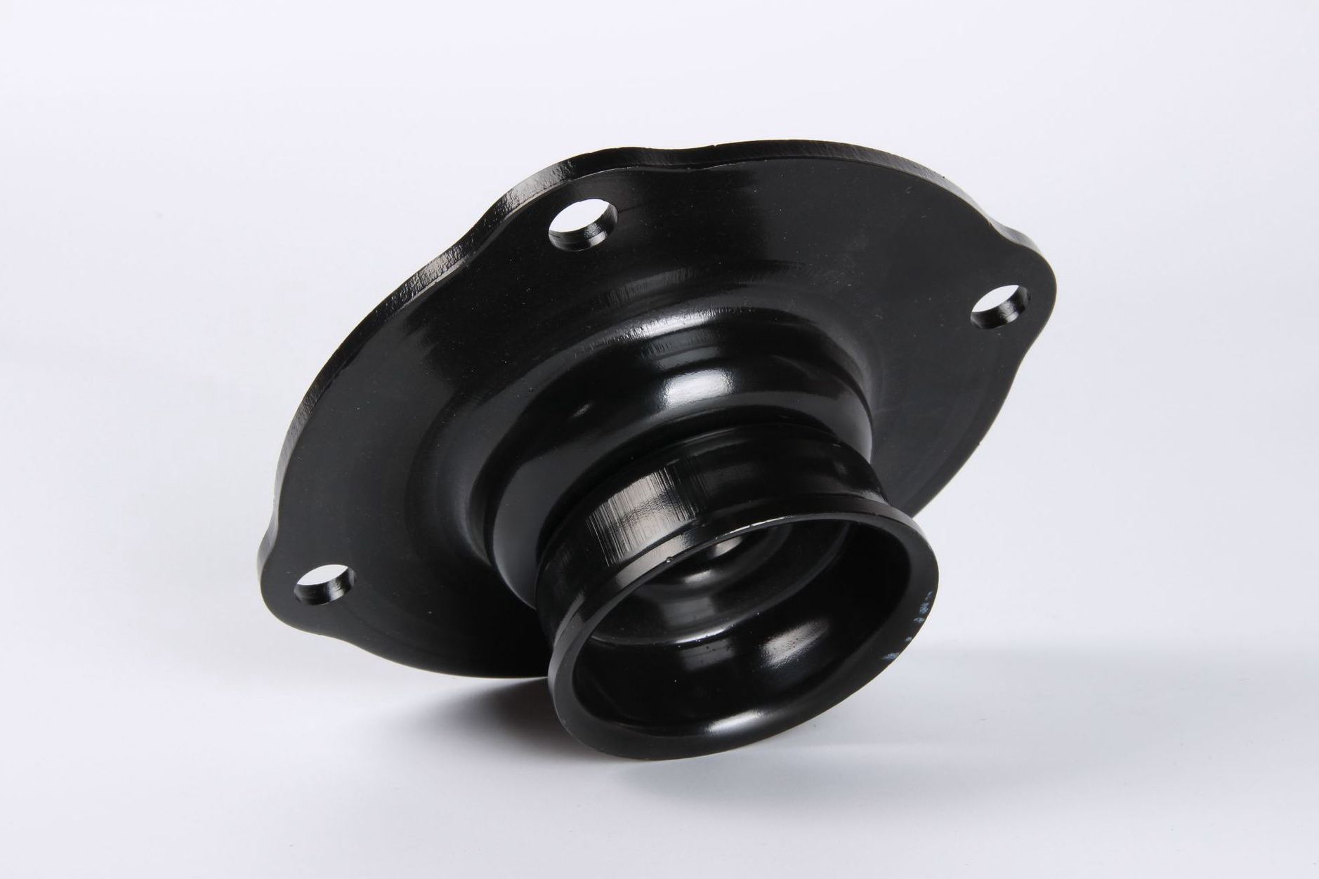
Laser cutting or plasma cutting can create blank profiles, slots, holes, and cutouts. Metal bending forms flanges, channels, boxes, brackets, and structural shapes. Sheet metal stamping can create repeated pierced, formed, or drawn features when tooling is justified.
These processes are often combined. A bracket may be laser cut and bent. An enclosure may be cut, bent, welded, fitted with hardware, powder coated, and assembled. A stamped feature may be added when repeated geometry makes tooling practical.
How do welding, hardware, and assembly expand sheet metal use?
Welding, riveting, PEM hardware, threaded inserts, hinges, fasteners, and assembly operations allow sheet metal parts to become stronger frames, enclosures, or multi-part assemblies. The joining method should match the load, vibration, corrosion exposure, access, cosmetic requirement, and inspection method.
Welded sheet metal parts need fixture planning and distortion control. Hardware insertion needs material thickness, hole preparation, and pull-out or torque requirements. Assemblies need datum control and fit checks so the final product aligns with mating components.
What finishes are used for sheet metal applications?
Surface finishing may include powder coating, painting, plating, anodizing, polishing, brushing, passivation-type treatment, or other buyer-specified finishes. Finish selection should match corrosion exposure, cosmetic class, coating thickness, texture, color, grounding needs, and final dimensional condition.
Coating can change fit. Threaded holes, PEM hardware, sliding surfaces, sealing areas, and grounding contact points may need masking or post-finish inspection. Buyers should state whether dimensions are measured before or after finishing.
What inspection evidence supports sheet metal applications?
Inspection evidence may include first article inspection, dimensional report, CMM inspection, bend angle report, flatness check, go/no-go gauge, weld inspection, hardware pull-out test, torque test, coating thickness report, visual inspection standard, material certificate, and assembly fit check.
The required evidence depends on the application. A decorative cover may focus on visual quality and coating. A mounting bracket may focus on bend angle, hole position, flatness, and material grade. An enclosure may need dimensional control, grounding points, hardware fit, and finish inspection.
Application Example | Sheet Metal Features | Manufacturing Risk to Check | RFQ Information Needed |
Electrical enclosure | Panels, flanges, holes, vents, covers, hinges, grounding points, and coating | Assembly mismatch, coating build-up, grounding contact, and cosmetic defects | Material, thickness, finish, hardware, grounding, IP or sealing requirement if specified, and inspection plan |
Mounting bracket | Bends, holes, slots, ribs, tabs, and load-bearing flanges | Springback, hole deformation, cracking, burrs, and load-path failure | Bend radius, bend angle, load direction, hole tolerance, material grade, and surface finish |
Machine guard or cover | Large panels, bends, cutouts, louvers, fasteners, and painted surfaces | Flatness, warpage, edge burrs, scratch marks, and coating damage | Panel size, edge requirements, cosmetic class, finish, assembly clearance, and packaging needs |
Chassis or frame | Welded or fastened structure, brackets, slots, datum surfaces, and inserts | Weld distortion, fixture error, datum movement, and assembly stack-up | Weld symbols, datum scheme, hardware list, flatness, alignment, and inspection report |
Stamped sheet metal part | Pierced holes, drawn shapes, embossed features, tabs, and repeated forms | Tooling cost, thinning, wrinkling, burr direction, and dimensional drift | Quantity, material, feature geometry, tooling approval, burr direction, and sample plan |
What should buyers provide for a sheet metal application RFQ?
A useful RFQ should include the 2D drawing, 3D model, flat pattern if available, application environment, material grade, sheet thickness, quantity, bend radius, bend angles, hole tolerances, hardware list, weld symbols, cosmetic surfaces, surface finish, coating thickness, assembly interfaces, and inspection method.
If the application could be made by machining, casting, extrusion, or fabrication, the buyer should identify the functional surfaces first. The supplier can then compare process routes against the same drawing and acceptance criteria.
Related FAQs