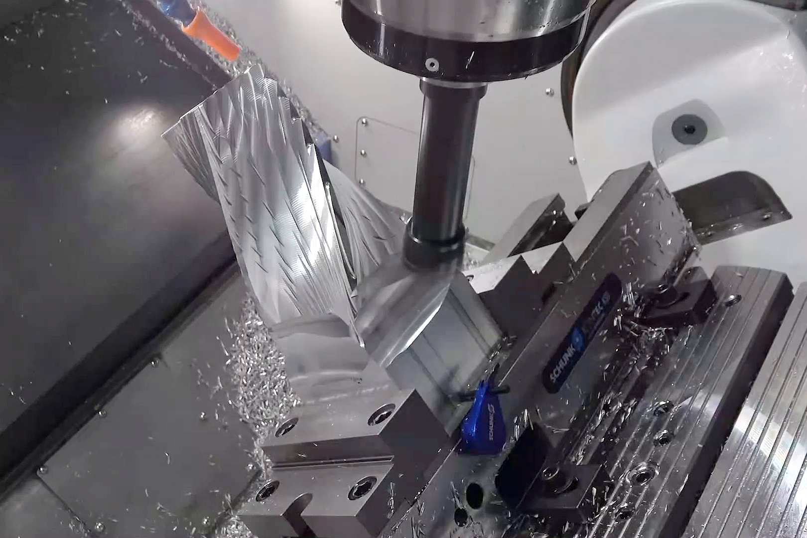
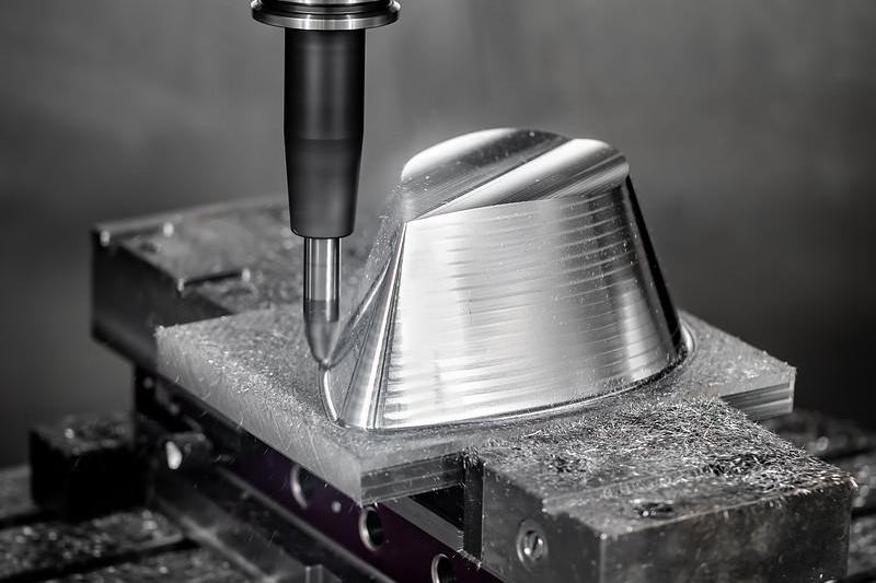
Unlock Design Flexibility with Multi-Axis CNC Machining Service
Multi-Axis CNC Machining Design Flexibility RFQ Decision: This article explains when buyers should consider multi-axis CNC machining prototyping for complex housings, angled brackets, manifolds, heat sinks, fixtures, curved covers, and precision machined components. The practical RFQ problem is defining which angled features, datum relationships, surface zones, material grades, tolerance priorities, and inspection methods require a multi-axis machining route instead of a simpler setup plan.
Multi-axis CNC machining can expand design options because the tool can approach the workpiece from several directions. That flexibility is useful for angled holes, compound surfaces, undercut-like access, blended contours, and features spread across multiple faces. Buyers still need a clear drawing, because design freedom does not remove the need for datum control, tool access review, burr planning, and inspection criteria.
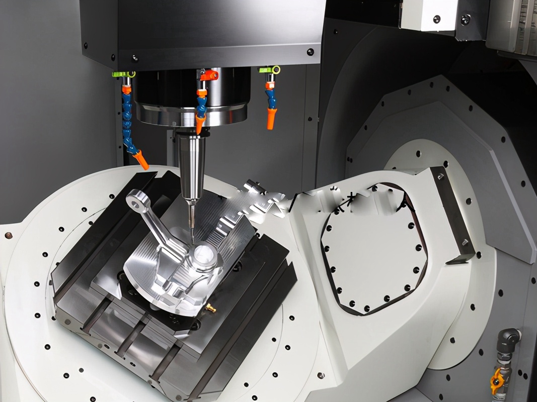
When Does Multi-Axis CNC Machining Add Design Flexibility?
Multi-axis CNC machining adds design flexibility when several critical features cannot be reached efficiently from one or two standard directions. A part with angled holes, curved faces, intersecting ports, or tight feature relationships may benefit from fewer re-clamping steps and better access to difficult surfaces.
The buyer decision should start with the part function. If angled features control assembly, fluid flow, heat transfer, motion, or alignment, multi-axis machining may help preserve the relationship between those features. If the part only has simple planar pockets and holes, conventional CNC milling may be more appropriate.
Buyers can support this decision by marking the functional faces and features on the drawing. The RFQ should identify which features must maintain orientation to the main datum and which features can be adjusted for manufacturability.
Which Part Features Usually Drive Multi-Axis CNC Selection?
Part features that usually drive multi-axis CNC selection include angled holes, compound contours, intersecting bores, sculpted surfaces, side-access pockets, tilted bosses, ported manifolds, and precision features distributed around several faces. These features can require extra setups on simpler equipment, and every setup can introduce alignment and handling risk.
Multi-axis machining can reduce some setup changes, but the design must still allow tool reach, cutter clearance, stable clamping, and chip evacuation. A deep feature with a small corner radius can remain difficult even on a multi-axis machine. The RFQ should include a native 3D model so the supplier can review access and propose realistic tool paths.
Multi-Axis Feature Entity | Manufacturing Reason | RFQ Detail To Provide |
|---|---|---|
Angled holes and tilted bosses | Feature orientation must match the datum scheme | Angle callouts, datum references, and inspection method |
Compound surfaces | Toolpath access and surface continuity affect finish | 3D model, surface finish zones, and acceptable tool marks |
Intersecting ports or bores | Internal relationships can affect flow, assembly, or alignment | Bore relationship, edge condition, and deburring requirement |
Features on several faces | Setup count can affect datum control and repeatability | Primary datums, critical relationships, and inspection records |
How Should Datums Be Defined For Multi-Axis CNC Parts?
Datums should be defined before selecting a multi-axis CNC route because the datum scheme controls workholding, tool orientation, and inspection. A complex part may have many visible features, but only some features control assembly. The drawing should identify primary, secondary, and tertiary references clearly.
For example, a machined housing may use a mounting face as the primary datum, a locating bore as the secondary datum, and a side face as the tertiary datum. Angled holes, sealing grooves, and threaded features should reference those datums if those relationships are functional. This lets the supplier plan the machining route around the same feature priorities the buyer will inspect.
When datums are unclear, the supplier may choose a convenient setup reference that does not match the buyer's assembly logic. Clear datum definitions make the quote more comparable and reduce the risk of disagreement during first article inspection.
How Does Material Choice Affect Multi-Axis Machining?
Material choice affects multi-axis machining because cutting force, tool wear, heat, burr formation, and part movement vary by material. Aluminum alloys may support efficient contour machining but still need support for thin ribs and cosmetic surfaces. Stainless steel may need more attention to tool wear, burrs, and heat. Copper alloys may require burr control and surface protection. Engineering plastics may require review for clamping and heat sensitivity.
The RFQ should state the exact material grade, temper or condition, approved substitute materials if any, and required documentation. If the design has thin walls, long projections, or complex pockets, the buyer should ask for manufacturability feedback on stock allowance, clamping, and machining sequence.
Secondary finishes should also be included early. Anodizing, passivation, bead blasting, plating, polishing, and coating can change surface preparation, edge break, masking, and inspection. A multi-axis CNC route should be planned with the final surface condition in mind.
How Do Tolerances And Surface Finish Change The Quote?
Tolerances and surface finish change the quote because complex geometry often requires a balance between machining time, inspection effort, and functional need. Buyers should identify the surfaces that control fit, sealing, movement, heat transfer, or appearance. Non-critical surfaces should not carry the same precision requirements as datum-controlled functional features.
A drawing should separate critical dimensions from general tolerances. Surface finish callouts should be attached to specific faces or zones. If a machined surface will later be anodized, plated, passivated, blasted, or polished, that downstream process should be stated in the RFQ. The machining supplier can then plan allowance, edge condition, and inspection stage correctly.
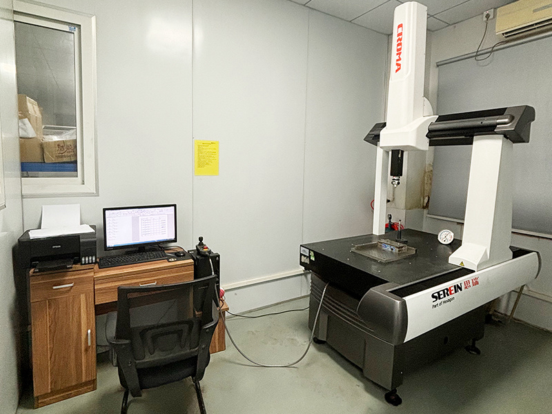
Inspection may involve coordinate measuring machine checks, optical inspection, thread gauges, pin gauges, surface roughness measurement, and first article reporting. The RFQ should state which records are required and which features need documented verification.
What Are The Main RFQ Risks With Multi-Axis CNC Parts?
The main RFQ risks are unclear design intent, inaccessible features, unrealistic internal radii, unsupported thin walls, excessive tolerance coverage, difficult deburring, and inspection ambiguity. These risks can appear even when the part is a strong candidate for multi-axis machining.
Buyers should ask the supplier to review tool access, clamping, datum transfer, surface finish, burr direction, and inspection feasibility before freezing the design. This is especially important when the part combines angled features, thin sections, and cosmetic faces.
Multi-Axis CNC Risk | Part Area Affected | Buyer Action Before Quotation |
|---|---|---|
Tool access conflict | Deep pockets, side features, and internal corners | Share 3D model and mark features with flexible radii |
Datum ambiguity | Angled holes, bores, mounting faces, and compound surfaces | Define datum scheme and functional feature relationships |
Burr and edge control | Intersecting holes, ports, slots, and handled edges | State deburring requirements and acceptable edge condition |
Surface finish mismatch | Cosmetic faces, sealing surfaces, and post-finished zones | Mark finish zones and describe secondary operation scope |
How Should Buyers Compare Multi-Axis CNC With Other Routes?
Buyers should compare multi-axis CNC with other CNC routes by feature relationship, setup count, inspection requirements, and production stage. CNC milling may be enough for planar parts. CNC turning may be enough for round parts. Mill-turn machining may be suitable when round features and milled details are both important. Multi-axis CNC is most useful when feature access and orientation are central to the part function.
The comparison should include manufacturability rather than only machine capability. A design may be technically possible but inefficient if the part requires extreme tool length, unstable clamping, or difficult inspection. A supplier review can identify design changes that preserve function while making the machining route more practical.
Buyers can use CNC milling service guidance and CNC turning process guidance to compare simpler route options before choosing multi-axis machining.
What Should A Multi-Axis CNC RFQ Include?
A multi-axis CNC RFQ should include the 3D model, 2D drawing, material grade, production stage, quantity range, datum scheme, angled feature callouts, critical dimensions, tolerance priorities, surface finish zones, secondary operations, inspection records, and packaging requirements. The RFQ should also identify which design features are fixed and which features may be adjusted for manufacturability.
Buyers should state whether the goal is prototype validation, design verification, bridge production, or repeat production. Prototype work may allow design changes after machining feedback. Repeat production may require more detailed fixture planning, inspection sampling, and process documentation.
Multi-axis CNC machining is most valuable when design flexibility is connected to clear functional requirements. A complete RFQ helps the supplier choose a route that protects critical geometry, controls inspection risk, and keeps the part manufacturable.
Related FAQs
What are common CNC machining methods used for precision parts?
What design rules should buyers review for CNC machined prototypes and parts?
How does CNC machining ensure part consistency and repeatability?
Which materials are best suited for CNC machining in critical applications?
What types of surface finishes can be achieved with CNC milling?