What Is Multi-Axis Milling? Its Classifications, Process, and Advantages
Multi-Axis Milling RFQ Decision: Multi-axis milling is a CNC milling route that uses linear and rotary machine axes to reach angled faces, multiple sides, undercuts, complex contours, and tight datum relationships with fewer setups. Buyers usually review multi-axis milling for housings, impellers, brackets, manifolds, mold inserts, fixture parts, and complex machined prototypes. The practical RFQ problem is deciding whether 3-axis milling is enough or whether 4-axis indexing, 5-axis positioning, or simultaneous 5-axis machining is needed for tool access, accuracy, surface finish, and inspection.
Multi-axis milling should be selected because the geometry or datum strategy requires it, not because the term sounds more advanced. Buyers should define angled holes, contour surfaces, undercuts, mating faces, critical datums, material grade, surface finish, quantity, and inspection evidence before requesting a quote.
What Multi-Axis Milling Means for RFQ Routing
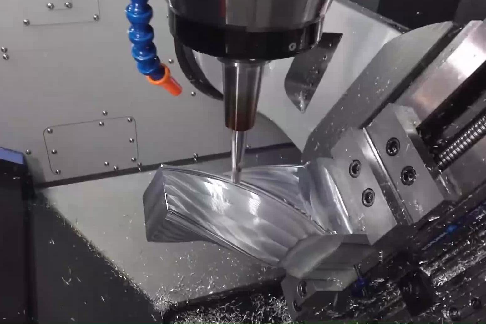
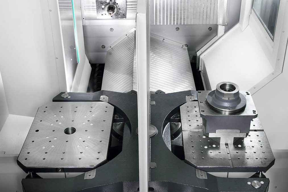
Multi-axis milling adds rotary motion to standard CNC milling. A 3-axis machine moves along X, Y, and Z. A 4-axis machine adds one rotary axis. A 5-axis machine adds more positioning freedom so the tool can approach the part from different angles. Some jobs use indexed positioning, while others use simultaneous motion.
The buyer question is what the extra axes must solve. Multi-axis milling may reduce setups, improve access to angled features, keep datums in one setup, shorten long tool reach, or improve surface continuity on complex contours. If the part is mostly flat pockets and vertical holes, standard CNC milling may be more practical.
How 3-Axis, 4-Axis, and 5-Axis Milling Differ
3-axis milling is commonly used for flat faces, pockets, slots, hole patterns, and simpler prismatic parts. 4-axis milling can rotate the workpiece to machine several sides or cylindrical features with fewer setups. 5-axis milling can position the tool relative to angled faces, sculpted surfaces, and complex geometry.
Simultaneous 5-axis milling is not the same as indexed 5-axis positioning. Indexed milling locks the rotary axes at certain angles before cutting. Simultaneous milling moves rotary and linear axes together during cutting. Buyers should not specify simultaneous machining unless the part surface, tool access, or finish requirement actually needs it.
Which Part Features Justify Multi-Axis Milling
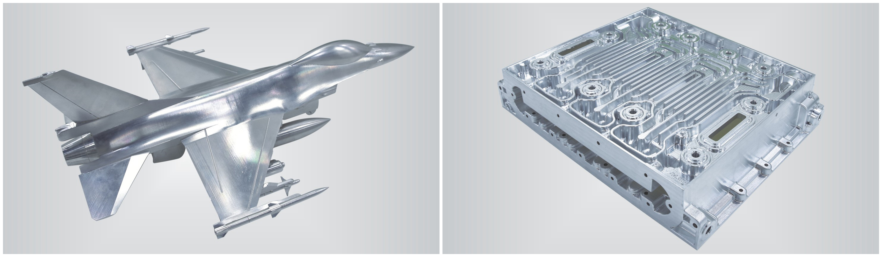
Multi-axis milling is usually reviewed when the part has angled holes, compound-angle faces, deep cavities, impeller-style blades, curved channels, turbine-like surfaces, undercuts, or several critical faces that must stay aligned. These features can be difficult to machine accurately with repeated 3-axis setups.
The RFQ should identify which features require multi-axis access and which surfaces are non-critical. Critical datums, sealing faces, bearing bores, mounting patterns, thin walls, and high-finish surfaces should be marked on the drawing. This allows the supplier to choose a fixture and toolpath strategy instead of assuming every surface has the same requirement.
How Workholding, Tool Access, and Datum Strategy Affect Accuracy
Workholding is central to multi-axis milling. A part may need fewer setups, but the fixture still must hold the part securely while leaving enough tool access. Thin walls, long overhangs, and complex shapes can vibrate or distort during machining. Tool length, holder clearance, collision risk, and chip evacuation can also limit the route.
Datum strategy should be defined before quotation. If a part has multiple mating faces, the buyer should identify which face controls assembly. If a hole pattern must align with an angled face, that relationship should be controlled on the drawing. Inspection planning should follow the same datum scheme.
Which Materials, Finishes, and Inspection Requirements Matter
Material selection affects cutting force, tool wear, heat, burrs, and surface finish. Aluminum, stainless steel, carbon steel, titanium, brass, copper alloys, engineering plastics, and superalloys can all require different toolpath and coolant strategies. The RFQ should define the material grade, not only the material family.
Surface finish and inspection requirements can change the machining route. A sculpted exterior surface may need fine step-over and polishing. A sealing surface may need controlled roughness and flatness. A threaded hole may need a gauge check. A complex datum relationship may need CMM inspection.
Multi-Axis Feature | Manufacturing Risk | RFQ Detail Needed | Inspection Evidence |
|---|---|---|---|
Angled hole pattern | Position error, tool access conflict, or burrs on exit. | Hole angle, datum scheme, thread requirement, and mating hardware. | CMM report, pin gauge, or thread gauge when required. |
Deep cavity with curved wall | Chatter, tool deflection, surface marks, or poor chip evacuation. | Cavity depth, corner radius, surface finish, and tool access allowance. | Dimensional report and surface inspection. |
Multiple mating faces | Setup stack-up error or inconsistent datum relationship. | Primary datum, mating surfaces, flatness, and perpendicularity requirements. | CMM report and assembly fit check if required. |
Thin wall or blade-like feature | Vibration, distortion, or inconsistent thickness. | Wall thickness, material grade, acceptable support strategy, and finish requirement. | Thickness check, visual inspection, and CMM report when required. |
What Neway Precision Reviews for Multi-Axis Milling RFQs
Neway Precision reviews multi-axis milling RFQs by checking the CAD model, drawing, material grade, angled features, undercuts, thin walls, datum scheme, fixture access, tool reach, surface finish, quantity, secondary operations, and inspection requirements. The review also considers whether CNC machining prototyping, 3-axis milling, 4-axis indexing, 5-axis positioning, simultaneous 5-axis machining, turning, grinding, or another route better supports the part.
A complete RFQ should include the 2D drawing, 3D model, material grade, quantity, critical dimensions, datum callouts, surface finish, heat treatment or finishing requirements, acceptable burr condition, and requested inspection records.
Related FAQs