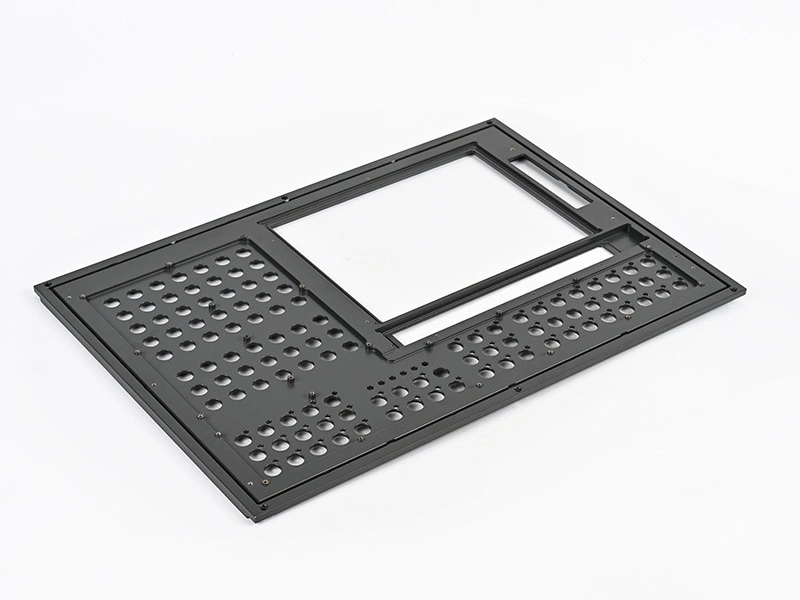
Top 18 Design Rules for CNC Machined Prototypes and Parts
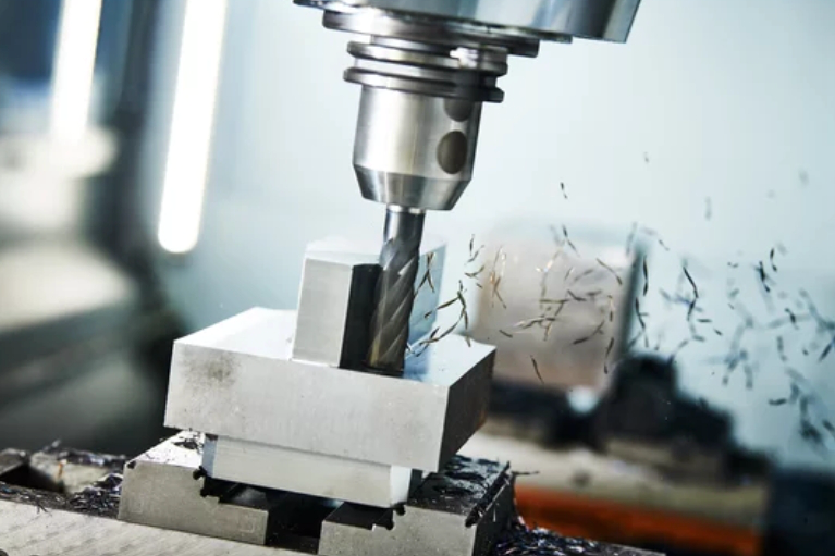
The CNC machining process is a subtractive manufacturing process. It obtains the designed model by removing raw materials with high-precision cutters. CNC machining prototyping service is suitable for prototype and small batch production. But in the design stage, we need to consider the following to avoid defects and low feasibility:
Wall Thickness
Avoid thin wall sections less than 0.04 in (1 mm) thick. Thin walls can deflect during machining and be fragile for handling. A minimum wall of 0.08 (2 mm) or more is recommended. Thicker walls over 0.25 in (6 mm) may require roughing passes to prevent tool deflection.
Internal Corners
Sharp internal corners often cannot be physically machined. Specify minimum radius corners of at least 0.04 in (1 mm). Larger internal fillets will be stronger. Allow clearance for cutting tool diameter. Very tight corners may need EDM or secondary grinding.
Exterior Corners
External sharp corners are possible but high-stress concentration points. Radiused corners of 0.02 (0.5 mm) or more significantly improve strength. Eliminate pointed external corners. Chamfers help part ejection from molds.
Ribs and Gussets
Add ribs and gussets to reinforce thin sections prone to vibration or deflection during machining. Locate ribs near clamping areas. Ribs help dissipate heat and improve part stability. Keep ends of ribs rounded.
Boss and Pad Heights
A minimum of 0.02 in (0.5 mm) thickness is recommended for small bosses and pads. Avoid long, thin posts and protrusions that can easily deflect. Provide clearance under overhangs for milling cutter diameters.
Hole Sizes
Limit hole diameters to no smaller than 1/8 in (3 mm). Holes below 0.04 in (1 mm) are challenging to machine and easily break small drill bits. Allow clearance for drill point angles.
Avoid Tiny Details
Fine details smaller than 0.010 in (0.25 mm) and delicate shapes will not fabricate well. Tiny text and logos turn into unreadable blobs. The minimum legible text height is 0.12 in (3 mm).
Tolerances
Specify reasonable tolerances that allow normal process variation. Allow +/- 0.005 in (0.127 mm) for general prototyping. Tighter tolerances incur more machining time and cost.
Surface Finishes
Finer surface finishes require more gradual stepovers and slower speeds/feeds. Commonly specified roughness values range from 125-250 microinches Ra. Finishes down to 32 Ra are possible.
Part Weight
More significant heavy components require greater fixturing and are prone to vibration at high speeds. Consider splitting large parts into segments to keep weight under 25 lbs (11 kg) each. Reduce mass where possible.
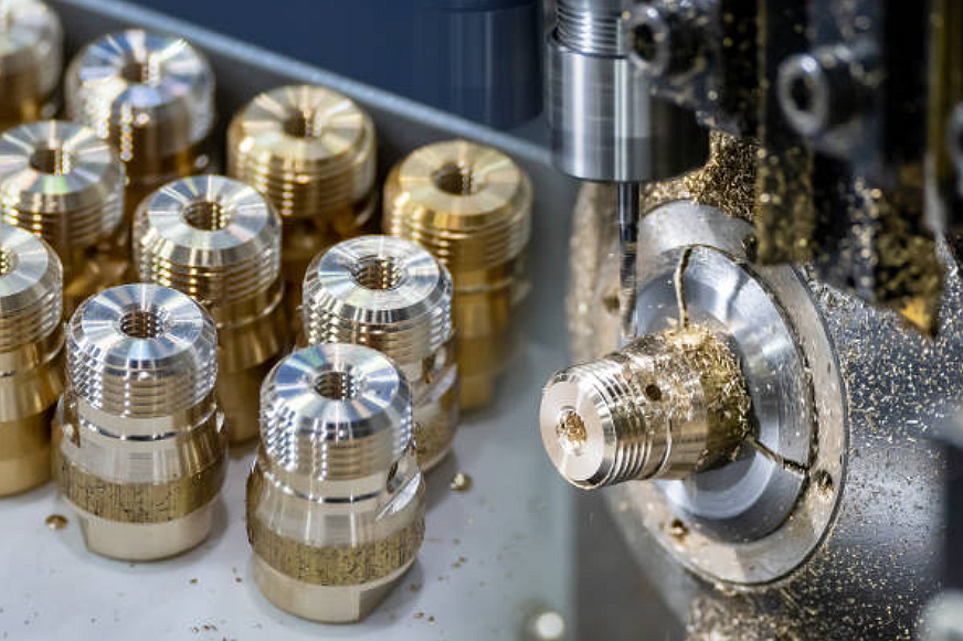
Material Selection
Use homogeneous, stable materials sized appropriately for the part dimensions. Avoid materials with large grain sizes relative to features. Hard metals have higher rigidity but are more challenging to machine.
Reducing Setup Time
Design to minimize complex fixturing and indexing to aid machinability. Combine multiple parts into one if appropriate. Standard fixture locating points speed loading.
Tool Accessibility
Provide suitable access for endmills to reach all internal corners and features. Limit deep blind pockets, bosses inside walls, and complex internal geometries. 5-axis machining improves accessibility.
Design for Manufacturability
Use proven design principles suited for machining processes. Avoid unnecessary operations. Standardize features used repeatedly on and between parts—design with production in mind.
Design Changes
Plan for design revisions and improvements. Make models parametric with key dimensions easily varied. CNC machining enables quick turnaround for design iterations. Keep change history and version control.
Draft Angles
Incorporate 1-2 degree draft angles on all vertical faces to allow part ejection from molds or fixtures. The draft angle helps pull cutting tools along the work surface.
Avoid Assemblies
Combining multiple components into one machined part when possible simplifies prototyping. Assemblies require the interfacing of components and hardware.
Standard Components
Use catalog standard hardware and purchased items where feasible instead of custom machined components. Standard fasteners, handles, hinges, gears, and accessories save cost.
Considering these design guidelines will help create CNC machined prototypes that machine efficiently, avoid tooling issues, meet tolerances, have appropriate finishes, and can be handled and assembled. The result is a faster turnaround and reduced prototyping costs.
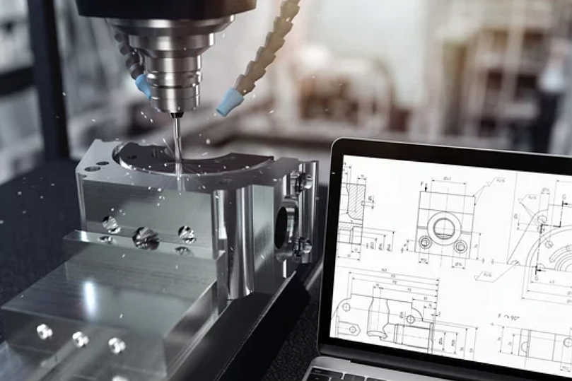
Custom CNC Machining Prototyping Service
Neway's meticulously engineered prototypes speak for themselves. Watch as their 5-axis CNC machines carve, contour, and craft your creations with micron-level precision. The Neway team meticulously inspects each prototype, ensuring dimensional accuracy and expertly tailored surface finishes. Receive your perfected prototypes in days, not weeks.