Reliable Electronic Component Manufacturing for Automotive
Automotive Electronic Component RFQ Decision: This article explains how buyers can specify automotive electronic component manufacturing using plastic injection molding, insert molding, metal injection molding, CNC machining, and prototyping. The practical RFQ problem is defining sensor housings, PCB metal casings, connector bodies, EMI shielding parts, brackets, clips, and sealed covers with clear material, insert, thermal, sealing, dimensional, and inspection requirements before quotation.
Which Automotive Electronic Part Is Being Quoted?
Buyers should define the electronic component function before selecting a manufacturing route. Automotive electronic RFQs may involve sensor housings, connector bodies, insert-molded terminals, PCB covers, metal shields, heat sink carriers, control unit brackets, cable guides, and small precision mechanisms.
The engineering reason is that these parts have different risks. A sensor housing may be controlled by sealing, connector alignment, and material stability. A PCB metal casing may be controlled by grounding, EMI shielding, flatness, and thermal path. An insert-molded connector may be controlled by metal insert position, resin flow, pull-out resistance, and moisture exposure.
For quotation, the buyer should separate electrical interfaces, sealing interfaces, mechanical datums, molded cosmetic faces, heat-transfer surfaces, threaded features, and inspection evidence. Vehicle-level reliability and final qualification remain buyer responsibilities, so the RFQ should state the part-level evidence needed from manufacturing.
Which Manufacturing Process Fits Automotive Electronics?
Process selection should follow part size, material, insert content, electrical interface, and production stage. Plastic injection molding, insert molding, metal injection molding, and CNC machining support different automotive electronic component decisions.
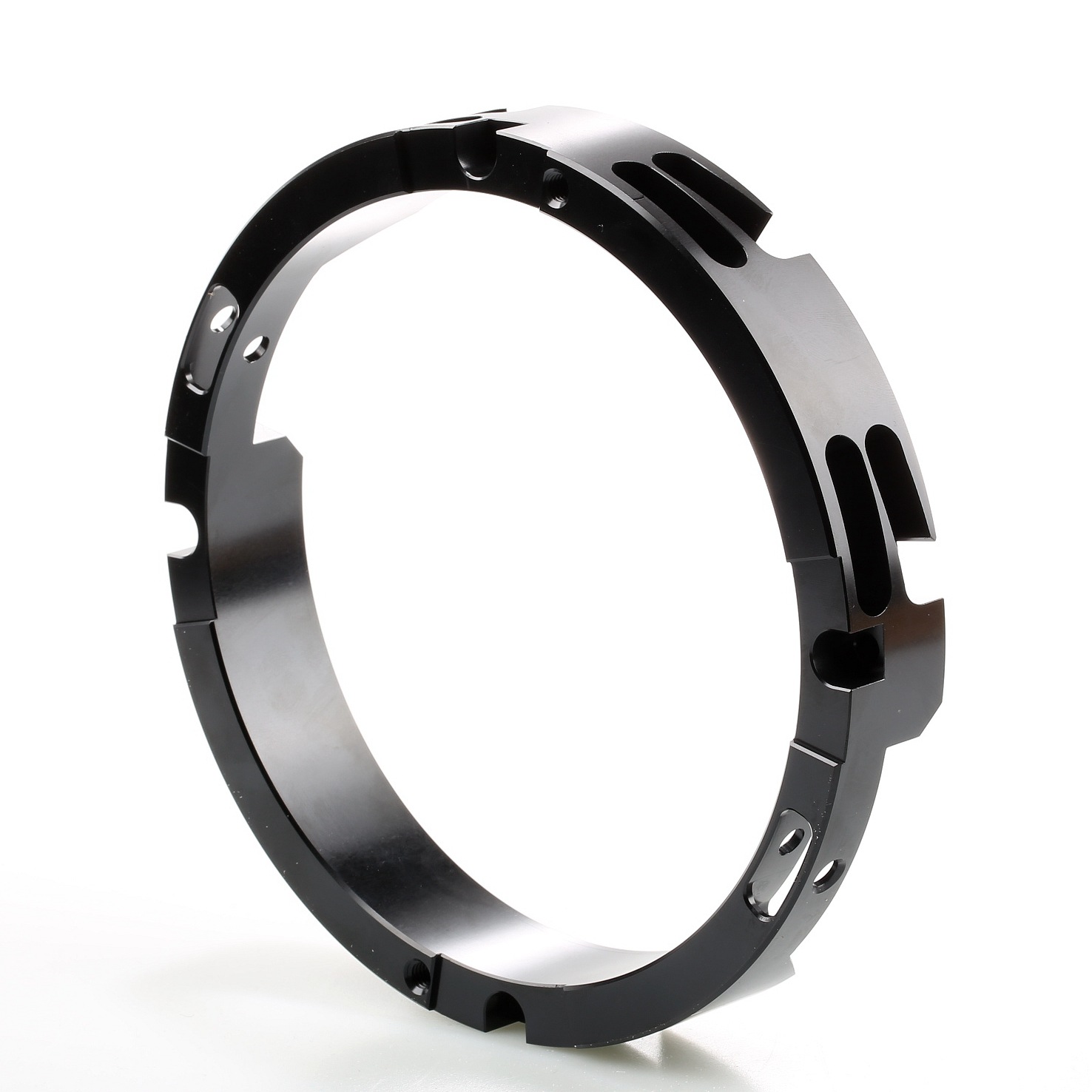
Manufacturing Process | Relevant Automotive Electronic Part | RFQ Decision Buyers Should State |
|---|---|---|
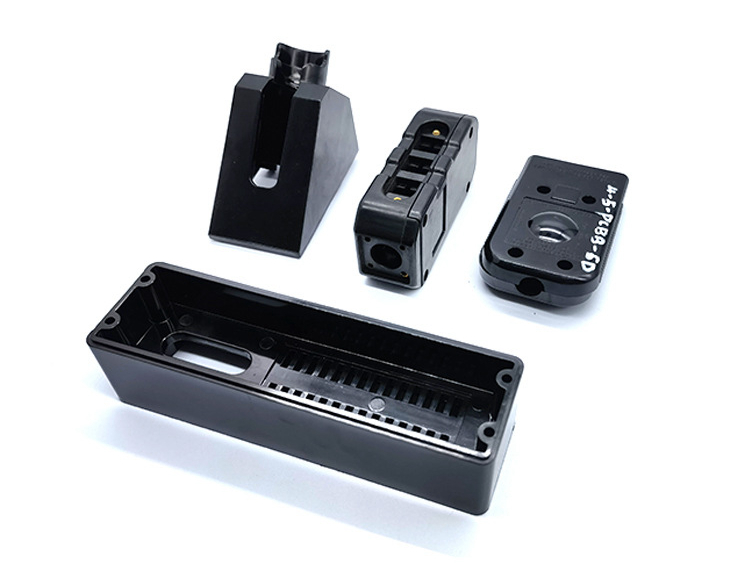
Plastic injection molding | Sensor housings, connector bodies, covers, cable guides, and insulating parts | Define resin grade, glass fiber need, wall thickness, ribs, bosses, warpage risk, and sealing features. |
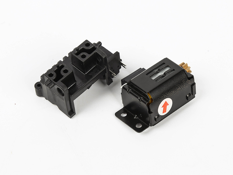
Insert molding | Connectors, terminals, threaded inserts, busbar features, and reinforced mounting points | Define insert material, insert position, exposed contact areas, pull direction, resin coverage, and inspection method. |
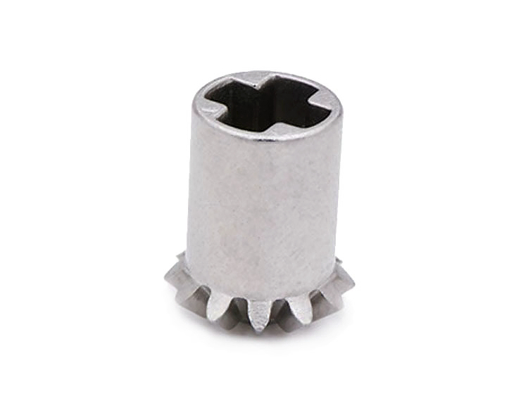
Metal injection molding | Small metal shields, brackets, mechanisms, lock parts, and compact conductive components | Define alloy, sintering control, datum surfaces, post-machining, heat treatment if required, and inspection report. |
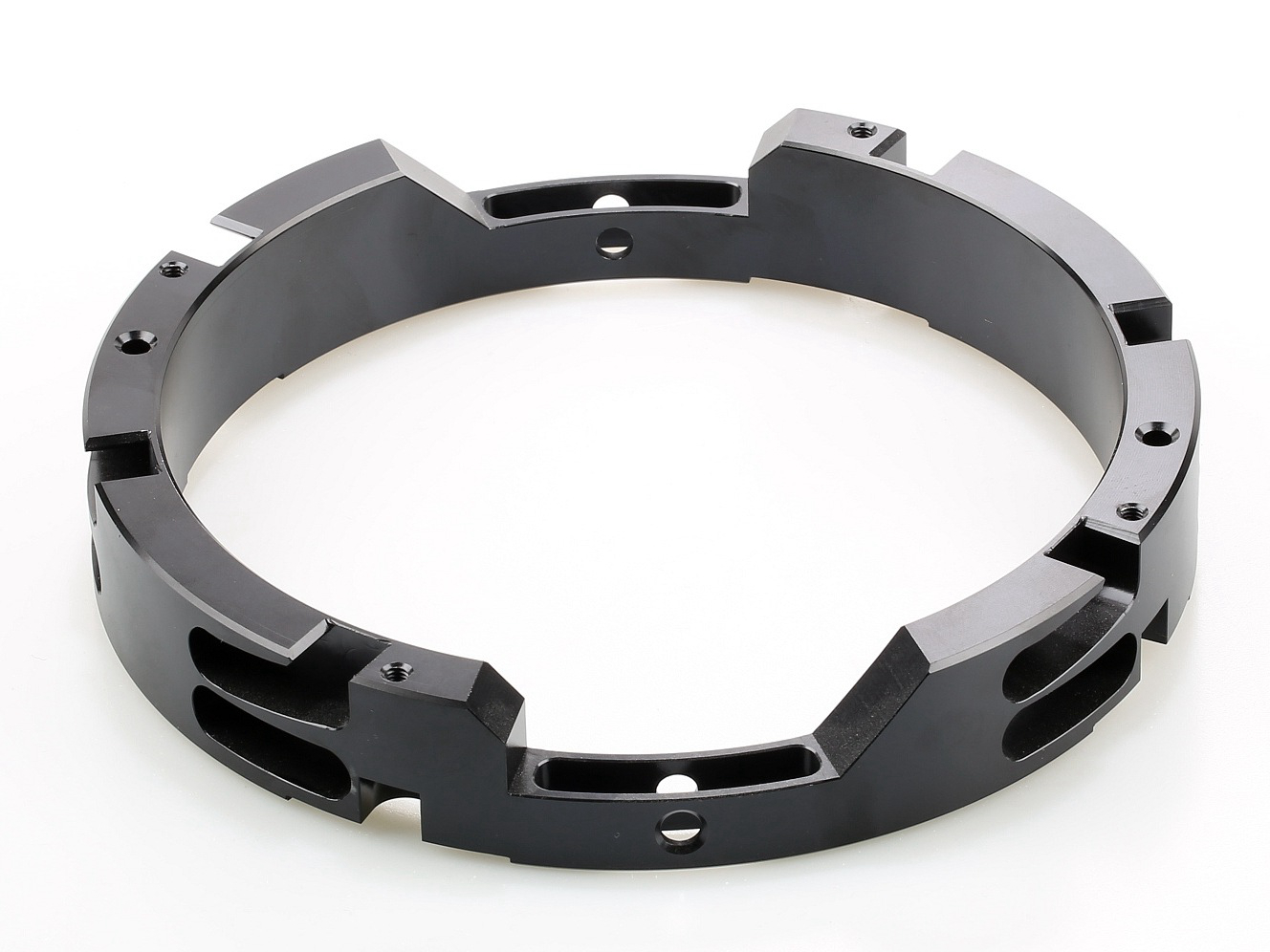
Prototype housings, metal casings, heat sink features, sealing faces, and precision interfaces | Define material, datum scheme, critical dimensions, surface finish, and prototype-to-production intent. | |
Fit-check electronics housings, connector samples, thermal mockups, and early design validation parts | Define the test purpose, revision status, inspection scope, and which production assumptions are still open. |
Which Materials Should Buyers Specify For Electronic Components?
Material choice should connect electrical function, thermal exposure, chemical exposure, dimensional stability, and assembly method. Automotive electronic parts may use engineering plastics, glass-filled resins, elastomers, stainless steel, copper alloys, aluminum alloys, or MIM stainless steel depending on the part function.
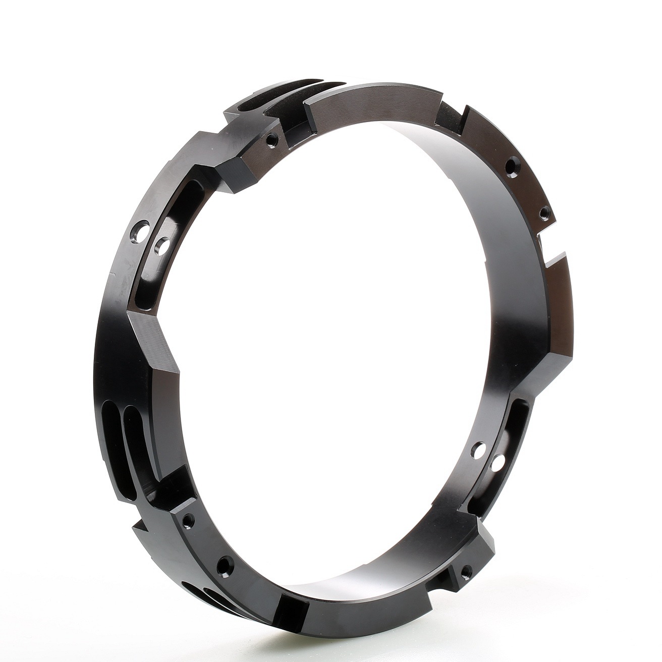
Material Entity | Common Electronic Component Requirement | Buyer RFQ Detail Needed |
|---|---|---|
Engineering plastic | Insulation, lightweight housing, connector body, and molded cover | Resin grade, reinforcement, color, surface finish, flame or heat requirement if applicable, and warpage control. |
Sensor housings, connectors, and parts exposed to heat or chemicals | Grade, glass fiber content, insert compatibility, dimensional stability, and sealing interface. | |
Stainless steel or MIM stainless steel | Small shields, brackets, lock pieces, conductive clips, and compact metal mechanisms | Grade, density requirement, datum features, finish, and post-machining need. |
Copper alloy or plated insert | Terminals, busbar elements, grounding contacts, and connector inserts | Insert geometry, plating, exposed area, contact surface, and molding protection requirement. |
Buyers should avoid vague material notes such as "automotive grade plastic" without a defined resin, test condition, or approval method. The RFQ should state whether the material is fixed by the buyer drawing or open for supplier review.
How Should Inserts, EMI Shielding, And Sealing Be Defined?
Insert molding should be specified with the metal insert and resin behavior together. Buyers should define insert material, plating, pre-molding cleaning need, insert orientation, exposed metal surfaces, overmold thickness, retention features, and inspection method for insert position.
EMI shielding should be defined by function, not by a general claim. If the component needs a conductive path, the RFQ should identify grounding areas, contact surfaces, shield geometry, coating masks, screw locations, and whether a buyer-side electrical test is required.
Sealing should be connected to the actual interface. Gasket grooves, O-ring lands, ultrasonic welding areas, adhesive zones, snap fits, threaded joints, and cable exits should each state dimensional and surface requirements. These details help prevent a molded housing from looking acceptable while failing at the assembly interface.
What Inspection Evidence Should Support The RFQ?
Inspection should match the component function. A molded connector, a MIM shield, and a CNC-machined prototype housing require different evidence, so the buyer should connect each inspection method to the relevant feature.
Inspection Entity | Relevant Method | Buyer Decision Supported |
|---|---|---|
Datum holes, connector faces, and mounting bosses | Confirm assembly alignment and precision interface geometry. | |
Molded housing shape and warpage | Compare molded, machined, or prototype geometry against CAD. | |
Metal alloy identity | Support alloy verification when metal shielding, inserts, or brackets require evidence. | |
Insert position and exposed contact areas | Fixture check, visual inspection, and section review if required | Confirm molded plastic does not cover functional terminal or grounding surfaces. |
What Should Buyers Include In An Automotive Electronics RFQ?
A complete RFQ should include the 2D drawing, 3D model, part function, resin or metal grade, insert material, exposed contact areas, sealing design, EMI requirement, thermal requirement, surface finish, critical dimensions, prototype or production stage, and inspection evidence.
The buyer should also state which requirements belong to manufacturing and which belong to vehicle-level validation. This makes the quote clearer for automotive electronic housings, connectors, PCB casings, shielding parts, and sensor components without implying that part manufacturing alone approves the final vehicle system.
Related FAQs