How to balance lightweight design with thermal performance in lighting systems?
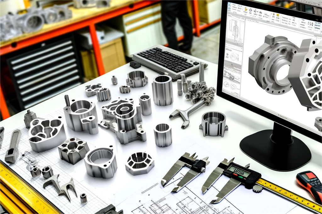
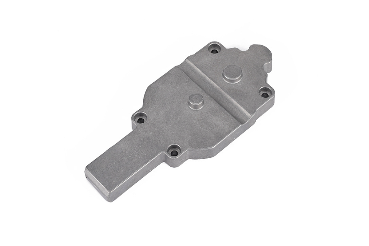
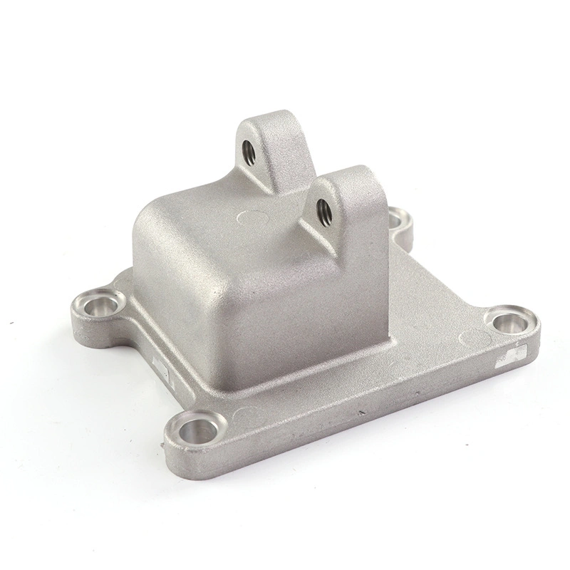
Balancing lightweight design with thermal performance in lighting systems means removing aluminum only where the material does not carry heat, stiffness, sealing load, or assembly accuracy. This FAQ explains how Neway reviews aluminum die casting, machined contact pads, fins, ribs, surface finishing, plastic-metal zoning, and prototype validation for LED housings, heat sink bodies, outdoor luminaires, and compact lighting modules. The practical RFQ problem is to define which weight reduction features are acceptable without weakening the heat path from the LED board to the aluminum housing and surrounding air.
Which material areas should not be reduced first?
Buyers should not reduce material first at the LED mounting pad, thermal interface area, screw bosses, sealing surfaces, datum features, or load-bearing ribs. These regions often control heat transfer, assembly repeatability, and product reliability more than overall part weight.
For lighting solution products, the aluminum die casting housing may act as a heat spreader, structural frame, sealed enclosure, and cosmetic shell at the same time. Weight reduction should therefore start with a functional zone map. The buyer should mark heat-spreading zones, airflow zones, sealing zones, screw zones, cable-entry zones, cosmetic surfaces, and noncritical pockets before Neway reviews wall thinning or rib removal.
Lighting housing zone | Weight reduction risk | RFQ control point |
|---|---|---|
LED mounting pad | Higher contact resistance and local hot spots | Flatness, roughness, machining allowance, and interface material |
Base wall under heat source | Lower heat spreading before heat reaches fins | Base thickness, alloy selection, and thermal simulation target |
Fins and airflow path | Reduced convection or blocked air movement | Fin spacing, fin height, orientation, and dust exposure |
Sealing and fastening features | Leakage, poor clamping, and beam alignment shift | Gasket groove, boss design, screw load, and assembly tolerance |
How do alloy choice and wall thickness affect weight and heat?
Alloy choice and wall thickness affect casting fill, porosity risk, mechanical stiffness, machining, surface treatment, and heat spreading. The buyer should choose an aluminum die casting alloy with the luminaire function and validation plan in mind, not only from a weight target.
Material pages such as A380, ADC12, A356, and B390 can support early alloy comparison for die cast lighting parts. Thin walls may reduce mass, but aggressive wall reduction can create fill problems, warpage, local porosity, or insufficient machining stock for LED contact pads. Neway reviews wall transitions, rib roots, boss bases, parting line, ejection direction, and machining datum before recommending a route.
How should fins, ribs, and hollow features be optimized?
Fins, ribs, and hollow features should be optimized by heat flow and casting feasibility together. A lighter luminaire body can still perform well when the design keeps material along the heat path and opens space where the material does little for heat transfer or stiffness.
Fin geometry should consider natural or forced airflow, dust, installation angle, cleaning access, die release, and trimming. Ribs should support stiffness and heat spreading without creating sink marks or blocked air paths. Hollow pockets can reduce weight when the pocket does not weaken the LED board support, gasket compression, screw load, or thermal path. The best RFQ drawings mark which regions are open for weight reduction and which regions are controlled by heat or assembly requirements.
Lightweight design feature | Thermal design implication | Die casting implication |
|---|---|---|
Thin fins | More surface area with possible airflow and dust limits | Fill, draft, breakage, and ejection review |
Hollow pockets | Lower mass with possible heat-spreading loss | Core, parting line, trimming, and porosity review |
Localized ribs | Stiffness support and possible heat bridge | Rib root radius, shrinkage, and machining clearance |
Machined contact pad | Lower interface resistance when flatness is controlled | Machining allowance, datum control, and burr control |
When do plastic-metal hybrid lighting parts help weight reduction?
Plastic-metal zoning can help when the plastic part does not carry the main heat path from the LED source. Nonthermal covers, wire guides, cosmetic caps, and selected brackets may use plastic injection molding, while the aluminum die cast body keeps the heat-spreading and heat-dissipation function.
This decision should be made at assembly level. Plastic components can reduce weight, improve insulation, or simplify appearance, but the design must protect heat flow, sealing, screw load, and optical alignment. Buyers should define which interfaces connect to the aluminum housing and whether the plastic part touches the LED board, driver, seal, lens, or cable gland.
How do surface finish, interface material, and machining affect the balance?
Surface finish, thermal interface material, and machining can decide whether a lightweight housing still transfers heat reliably. A lighter casting with poor contact or uncontrolled coating at the LED pad may perform worse than a slightly heavier design with a controlled interface.
Anodizing cast aluminum, painting, powder coating, conversion coating, and other surface finishing options should be reviewed with coated zones and masked heat-transfer zones clearly defined. Machined LED contact pads, threaded inserts, sealing grooves, and datum surfaces should be identified before prototype validation. The RFQ should also state the thermal interface material thickness, screw pattern, and assembly torque if those items affect the heat path.
What RFQ details confirm the weight and thermal tradeoff?
An RFQ should include 3D CAD, 2D drawing, target weight, LED power, controlled temperature point, alloy preference, wall thickness limits, fin geometry, plastic-metal boundary, machined contact zones, surface finish, coating masks, sealing requirement, airflow condition, prototype plan, production volume, and thermal validation method. These details allow Neway to review lightweight design, die casting feasibility, machining, surface finishing, assembly, and thermal testing together.
Buyers should also state whether the priority is lower mass, lower temperature, outdoor durability, optical alignment, appearance, or cost. That priority helps Neway identify which features can be lightened and which features should remain controlled for heat transfer and reliability.
Related FAQs
What parameters are vital for thermal design in high-power LED luminaires?
Can aluminum die casting be used for heat dissipation components?
How to choose active vs passive cooling for different lighting applications?
What factors most impact natural convection efficiency in heatsink design?
How does Neway verify long-term reliability of lighting thermal solutions?
What is the thinnest strong wall possible for aluminum die cast enclosures?
What surface finishes are suitable for aluminum die casting parts?