Boosting Strength with Insert Molding: A Game-Changer for Component Durability
Insert Molding Durability RFQ Decision explains how the insert molding process can improve component strength when metal or plastic inserts must be fixed inside a molded plastic part. The buyer decision is whether threaded inserts, bushings, terminals, shafts, pins, brackets, or reinforcement features should be molded into the part instead of being pressed, bonded, or fastened after molding. The practical RFQ problem is that insert material, resin grade, load direction, retention geometry, molding temperature, and inspection criteria must be clear before insert molding durability can be reviewed.
How Does Insert Molding Improve Component Strength?
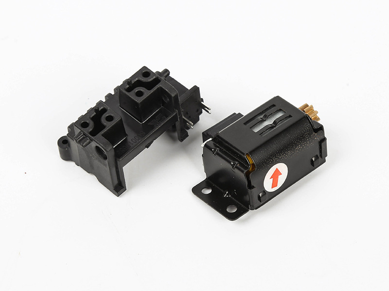
Insert molding improves component strength by locking a stronger insert into a molded plastic body during the molding process. The insert can carry threads, torque, electrical contact, wear surfaces, or fastening loads that the plastic alone may not support as reliably.
The strength improvement depends on the load path. A threaded brass insert for repeated screw assembly has a different risk profile than a steel shaft, a metal terminal, or a plastic reinforcement core. The molded resin must flow around the insert without moving it, cracking around it, or leaving weak bonding and retention areas.
For buyers, the most important decision is whether the insert carries load, locates another component, conducts electricity, resists wear, or reinforces a weak plastic zone. Each purpose changes the insert material, resin choice, tooling design, and inspection method.
Which Insert Types Should Be Defined Before RFQ?
The RFQ should define the insert type before quotation because insert shape and material affect mold loading, holding method, resin flow, and final part strength. A small threaded insert, a long pin, and a stamped terminal require different tooling and inspection logic.
Insert Type | Strength or Durability Function | RFQ Detail Needed |
|---|---|---|
Threaded metal insert | Supports repeated screw assembly and torque transfer | Thread standard, torque requirement, pull-out requirement, and insert material |
Metal bushing or sleeve | Controls wear surface, alignment, or rotating interface | Inner diameter, datum surfaces, mating component, and wear condition |
Electrical terminal or contact | Provides conductive path and stable terminal position | Terminal material, exposed contact area, insulation requirement, and position tolerance |
Pin, shaft, or rod | Provides alignment, hinge function, or load transfer | Load direction, exposed length, holding method, and critical straightness requirement |
Plastic or composite reinforcement | Improves stiffness or feature retention in a localized area | Material grade, geometry, interface area, and assembly load |
If the insert is customer-supplied, the RFQ should include insert drawings and material information. If Neway is expected to source the insert, the buyer should define the performance requirement and the accepted insert material options.
How Do Resin Materials Affect Insert Molding Durability?
Resin material affects insert molding durability because the plastic must hold the insert under heat, load, and assembly stress. The resin must also tolerate molding around the insert without excessive sink, cracking, warpage, or weak knit lines.
Common resin choices include ABS, nylon PA, PC, PP, POM, PPS, and PEEK depending on strength, temperature exposure, dimensional stability, and chemical environment. The best choice depends on the insert function and the buyer's application requirement.
Material mismatch can create durability risk. A metal insert expands differently from the plastic around it. A sharp insert corner can concentrate stress. A resin with poor flow around the insert can leave voids or weak weld lines. The RFQ should describe the operating environment, assembly load, and inspection requirement so material selection can be reviewed against the actual use condition.
What Design Features Improve Insert Retention?
Insert retention depends on mechanical locking, resin coverage, insert surface geometry, and load direction. A smooth insert surrounded by thin plastic may not resist pull-out or rotation as well as an insert designed with knurls, grooves, undercuts, holes, shoulders, or controlled surface features.
The molded plastic should have enough wall thickness around the insert to handle stress without cracking. The design should also avoid sharp resin corners where stress can concentrate during assembly. If the insert receives torque, pull-out load, bending load, or repeated assembly, the drawing should show the direction and acceptance criteria for those loads.
Insert Retention Feature | Manufacturing Purpose | Durability Risk if Undefined |
|---|---|---|
Knurl, groove, or undercut | Helps plastic mechanically lock around the insert | Insert may rotate or pull out under assembly load |
Shoulder or flange | Controls axial position and load distribution | Insert height may vary or local plastic may crack |
Controlled wall thickness around insert | Supports resin flow and stress distribution | Sink, cracking, voids, or weak weld lines may occur |
Defined datum and holding surface | Keeps insert aligned during molding | Insert shift can affect assembly fit and inspection results |
When Is Insert Molding Better Than Press-Fit or Post-Assembly?
Insert molding is often better when the insert must be accurately located, sealed into plastic, protected from loosening, or integrated before final assembly. Press-fit and post-assembly methods can be practical, but those routes add separate handling and may introduce alignment variation.
Insert molding can reduce secondary operations when the molded plastic must permanently capture the insert. It can also protect delicate terminal positions or combine metal strength with molded plastic geometry. However, insert molding requires the insert to be placed and held during molding, so the process must be evaluated for insert loading method, cycle time, and molding repeatability.
For parts already made through plastic injection molding, switching to insert molding changes the tool and production workflow. Buyers should compare insert molding with ultrasonic insertion, heat staking, press-fit assembly, adhesive bonding, or mechanical fastening when those alternatives are available.
What Failure Modes Should Buyers Prevent?
Buyers should prevent insert movement, pull-out, rotation, resin cracking, sink, voids, exposed sharp edges, and poor alignment. These failure modes can affect durability even when the molded part looks acceptable at first inspection.
Insert movement during molding can shift threaded holes or terminal locations. Pull-out and rotation can appear during screw assembly or service. Resin cracking can occur around stress concentration points. Voids or knit lines near the insert can reduce strength. Exposed metal edges can create assembly or safety issues if they are not part of the design.
The drawing should identify critical insert positions, load-bearing features, inspection dimensions, and any functional tests required by the buyer. If the part is used in automotive, consumer electronics, medical device, or tool applications, the buyer should define the product-specific acceptance criteria rather than relying on a generic durability statement.
How Should Insert Molded Parts Be Inspected?
Insert molded parts should be inspected for insert position, resin coverage, flash, sink, cracking, thread quality, exposed insert condition, and functional performance. The inspection method should match the purpose of the insert.
Dimensional inspection may check insert height, concentricity, hole position, exposed length, and datum alignment. Visual inspection may check resin flow around the insert, flash, gaps, and cosmetic defects. Functional inspection may include torque, pull-out, continuity, assembly fit, or buyer-defined durability validation. The specific acceptance criteria should be agreed before production release.
Inspection planning is especially important when insert molded parts include multiple inserts. The tooling must hold each insert repeatably, and the inspection plan must catch missing, shifted, reversed, or damaged inserts before downstream assembly.
What Neway Precision Reviews for Insert Molding Strength?
Neway Precision reviews insert molding strength by connecting insert material, resin grade, insert geometry, load direction, tooling concept, and inspection requirements. The review focuses on whether the molded part can hold the insert consistently through sampling and production.
A complete RFQ should include the 3D model, 2D drawing, insert drawing, insert material, resin material, load direction, assembly method, critical dimensions, expected production volume, and acceptance criteria. This information helps Neway evaluate whether insert molding, post-mold insertion, overmolding, or another manufacturing route is suitable.
Insert molding durability is strongest when the insert has a defined job and the plastic around the insert is designed for that job. Thread strength, terminal location, wear resistance, hinge support, and reinforcement all need different engineering decisions. Clear RFQ inputs help identify those decisions before tooling begins.
Related FAQs
What is insert molding and how does it differ from traditional molding processes?
How does insert molding improve the reliability of components?
What types of materials are most suitable for insert molding?
Are there limitations or challenges associated with insert molding?
What are the common challenges in insert molding and how can they be resolved?